Internal combustion engine control device

a control device and internal combustion engine technology, applied in electrical control, electrical control, reciprocating combination engines, etc., can solve the problems of increased torque fluctuation, increased torque fluctuation, and increased torque fluctuation of internal combustion engine torque, so as to reduce the fluctuation of torque more.

Active Publication Date: 2010-01-28
TOYOTA JIDOSHA KK
View PDF10 Cites 23 Cited by
  • Summary
  • Abstract
  • Description
  • Claims
  • Application Information

AI Technical Summary

Benefits of technology

[0006]The present invention provides an internal combustion engine control device that reduces fluctuation in torque more effectively when a rich spike is performed.

Problems solved by technology

In the structure in which the EGR gas is drawn from the exhaust passage downstream of the NOx adsorber catalyst, when a rich spike, i.e. a process of adding a reducing agent to the exhaust gas upstream of the NOx adsorber catalyst to reduce adsorbed substances such as SOx and NOx, is performed, the oxygen concentration in the EGR gas that is recirculated to the intake passage suddenly changes and the combustion in the internal combustion engine becomes unstable, resulting in a decrease in torque of the internal combustion engine.
However, if a rich spike is carried out while the torque fluctuation reducing device is reducing a fluctuation in torque of the internal combustion engine, the fluctuation in torque increases and the combustion in the internal combustion engine becomes unstable.

Method used


Image

  • Internal combustion engine control device
  • Internal combustion engine control device
  • Internal combustion engine control device

Examples


first embodiment

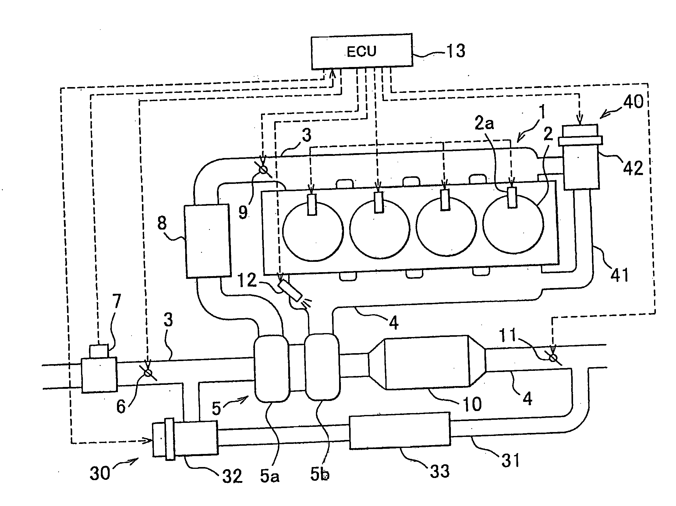
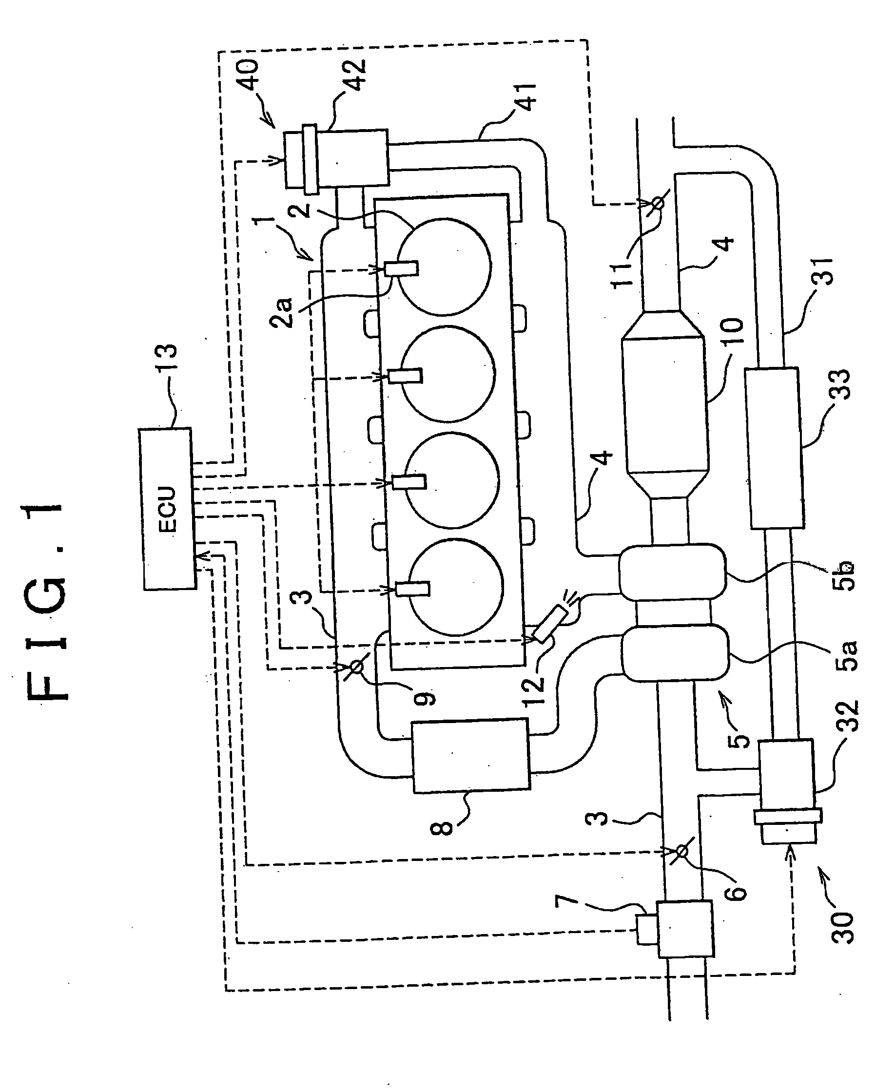
[0045]Therefore, in the first embodiment, a rich spike is inhibited while the torque fluctuation reducing operation is being performed to reduce a fluctuation in torque of the internal combustion engine 1.

[0046]According to the above method, because a rich spike is inhibited while the torque fluctuation reducing operation is being performed, there is no possibility that additional fuel is added during a torque fluctuation reducing operation to increase the fluctuation in torque. Thus, the fluctuation in torque of the internal combustion engine 1 may be reduced by performing a torque fluctuation reducing operation and the combustion in the internal combustion engine 1 is stabilized.

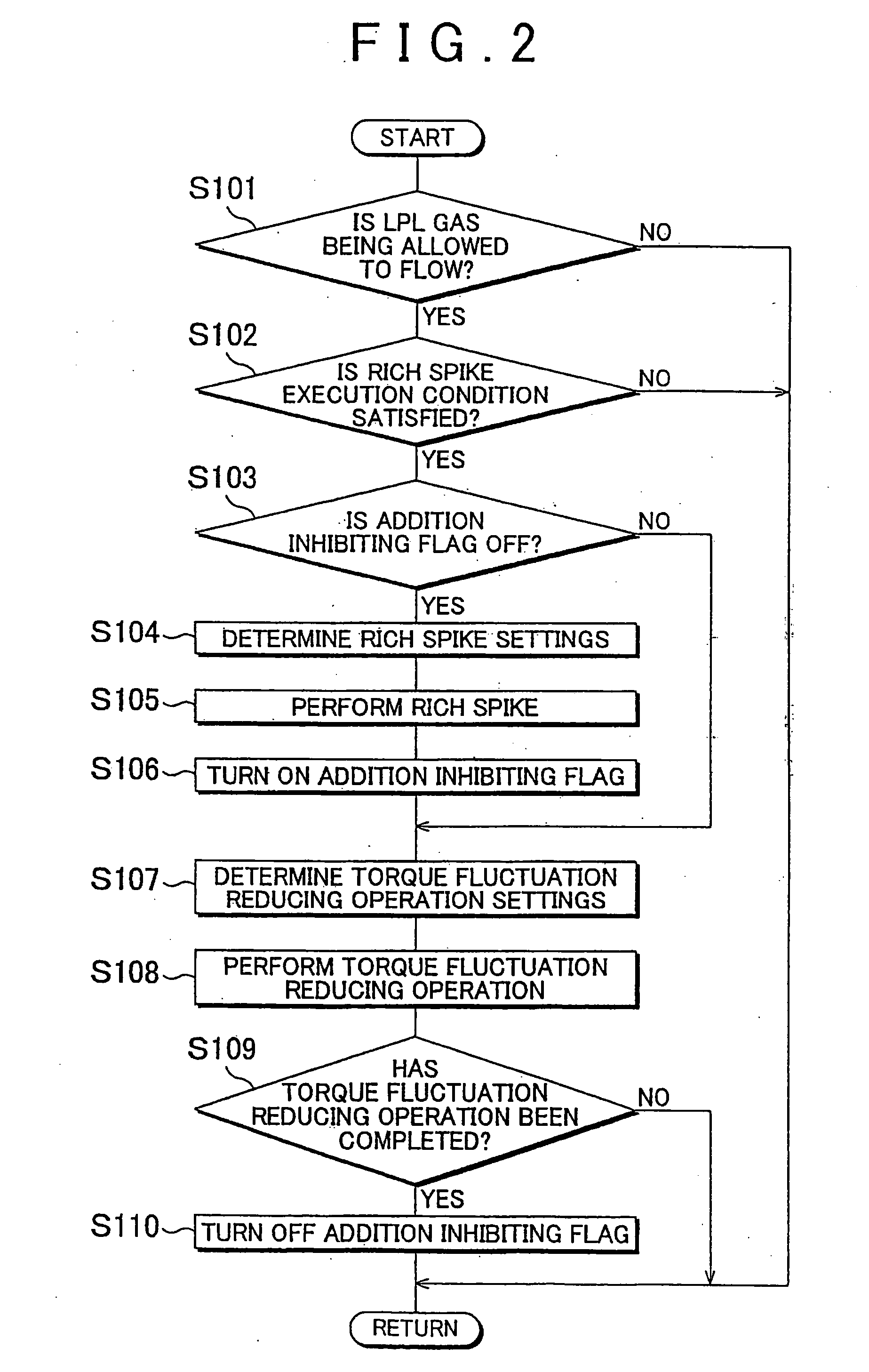
[0047]The control routine, which is executed when a rich spike is performed, according to this embodiment is next described. FIG. 2 is a flowchart of the control routine, which is executed when a rich spike is performed, according to this embodiment. This routine is repeated at specified time intervals.

[00...

second embodiment

[0064]Therefore, in a second embodiment, when fuel is added using the fuel addition valve 12 to reduce the NOx and SOx adsorbed by the NOx catalyst and the low-pressure EGR gas is recirculated through the low-pressure EGR passage 31, the amount of fuel to be added from the fuel addition valve 12 is reduced, which decreases the degree to which a fluctuation (decrease) in torque is reduced by the torque fluctuation reducing operation, and the second throttle valve 9 is controlled to reduce the amount of intake air to be supplied to the internal combustion engine 1. The decrease in torque of the internal combustion engine 1 from a steady state is compensated for by the assist of a motor 14 [“motor 14 is driven to compensate for the decrease in torque of the internal combustion engine 1 from a steady state.

[0065]According to the above method, because the amount of fuel that is added from the fuel addition valve 12 during a rich spike, during which the amount of fuel added by the fuel ad...


PUM


Abstract

An internal combustion engine control device includes a NOx adsorber catalyst disposed in an exhaust passage, an EGR passage, a reducing agent adding device, a torque fluctuation reducing device, and a fuel injection device. The EGR passage draws a portion of exhaust gas from the exhaust passage downstream of the NOx adsorber catalyst and recirculates the exhaust gas into the intake passage. The reducing agent adding device adds a reducing agent to exhaust gas upstream of the NOx adsorber catalyst to reduce substances adsorbed by the NOx adsorber catalyst. When or after the reducing agent adding device adds the reducing agent, the torque fluctuation reducing device advances the timing of the fuel injection device or carries out a pilot injection to reduce a fluctuation in engine torque. The reducing agent adding device adds less reducing agent while the torque fluctuation reducing device is operating.

Description

BACKGROUND OF THE INVENTION[0001]1. Field of the Invention[0002]The present invention relates to an internal combustion engine control device.[0003]2. Description of the Related Art[0004]Some internal combustion engines are provided with a turbocharger and a low-pressure EGR passage for drawing a portion of exhaust gas as low-pressure EGR gas from the exhaust passage downstream of the turbine of the turbocharger and downstream of a NOx adsorber catalyst (which is hereinafter referred to simply as “NOx catalyst”) into the intake passage upstream of the compressor of the turbocharger. Such internal combustion engines are also provided with a high-pressure EGR passage for recirculating a portion of exhaust gas as high-pressure EGR gas from the exhaust passage upstream of the turbine and recycling the high-pressure EGR gas into the intake passage downstream of the compressor. A technology for controlling the amount of low-pressure EGR gas flowing through the low-pressure EGR passage and...

Claims


Application Information

Patent Timeline
Patent Type & Authority Applications(United States)
IPC IPC(8): F01N9/00F01N3/04F01N3/10F02D41/00F02B3/00F01B21/04
CPCF01N3/0814F01N13/0097F01N3/0842F01N3/0871F01N3/0885F01N3/106F01N2240/36F01N2510/06F01N2610/03F02B29/0406F02B37/00F02D9/04F02D41/0055F02D41/0275F02D41/1497F02D41/401F02D41/403F02D2250/21F02D2250/24F02M25/071F02M25/0727F02M25/074Y02T10/146Y02T10/44F01N3/0821F02M26/07F02M26/23F02M26/35Y02T10/12Y02T10/40
Inventor MATSUMOTO, ISAOSAODA, TAKENORIMAGARIDA, NAOFUMIMURATA, HIROKIYAMASHITA, AKIRAHAGA, HIROYUKI
Owner TOYOTA JIDOSHA KK
Why Eureka
Try Eureka