Gas measuring apparatus and gas measuring method

a technology of gas measuring apparatus and measuring method, which is applied in the direction of optical radiation measurement, interferometric spectrometry, instruments, etc., can solve problems such as inability to us

Inactive Publication Date: 2010-01-28
NEC CORP
View PDF3 Cites 25 Cited by
  • Summary
  • Abstract
  • Description
  • Claims
  • Application Information

AI Technical Summary

Problems solved by technology

Therefore, in the technique described in non-patent document 1, the usable infrared sensor is restricted, and thereby it is not possible to use, for example, a two-dimensional infrared detector having a cutoff wavelength of 11 micrometer.

Method used


Image

  • Gas measuring apparatus and gas measuring method
  • Gas measuring apparatus and gas measuring method
  • Gas measuring apparatus and gas measuring method

Examples


Embodiment Construction

)

[0035]In the following, exemplary embodiments according to the present invention will be described with reference to the accompanying drawings.

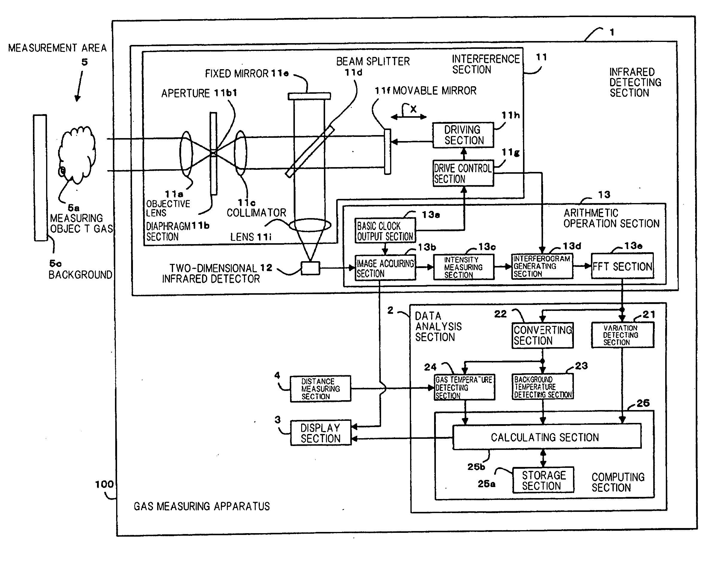
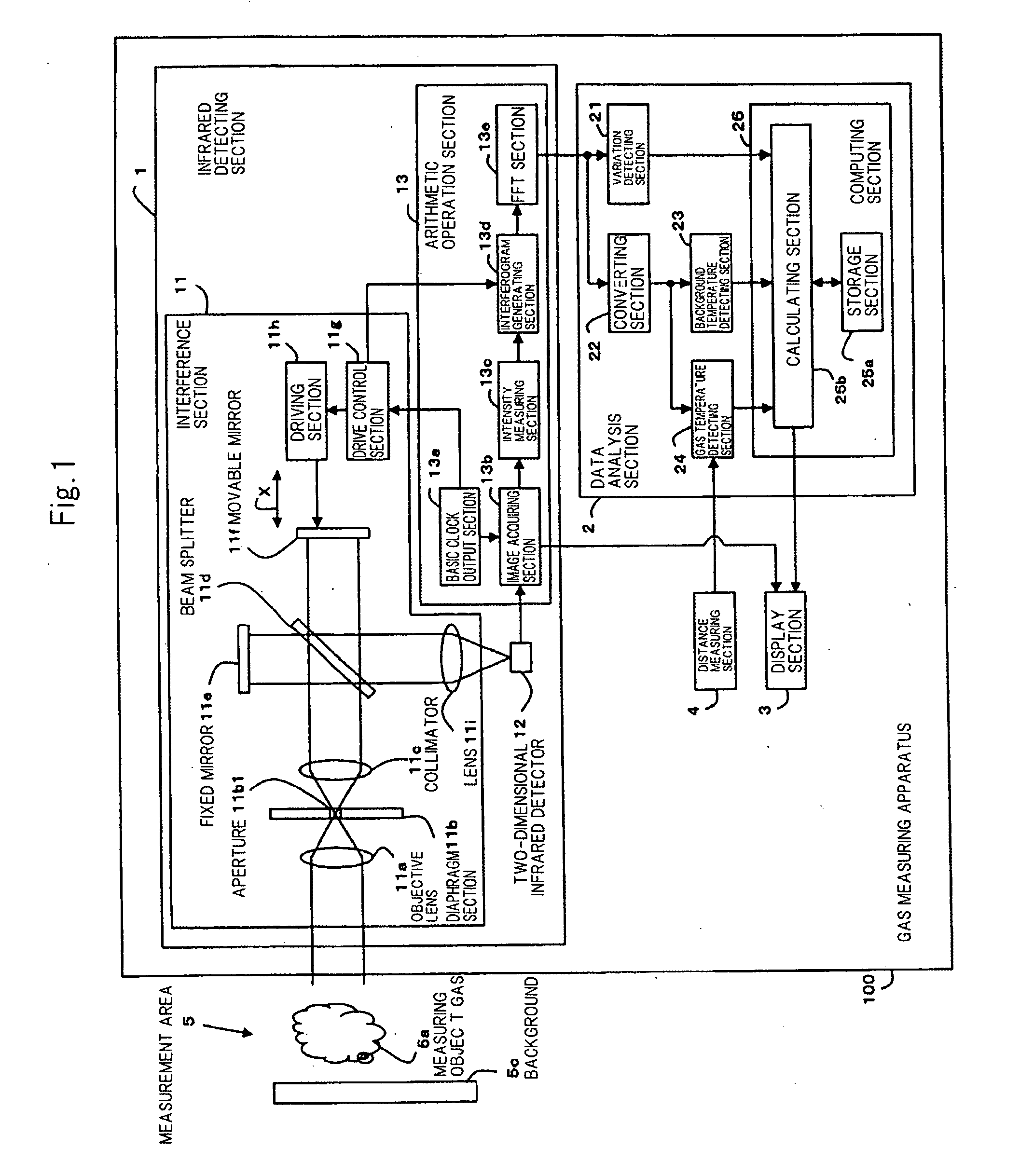
[0036]FIG. 1 is a figure showing gas measuring apparatus 100 according to a first exemplary embodiment.

[0037]In FIG. 1, gas measuring apparatus 100 includes infrared detecting section 1, data analysis section 2, display section 3, and distance measuring section 4.

[0038]Infrared detecting section 1 includes interference section 11, two-dimensional infrared detector 12, and arithmetic operation section 13.

[0039]Data analysis section 2 includes variation detecting section 21, converting section 22, background temperature detecting section 23, gas temperature detecting section 24, and computing section 25. Computing section 25 includes storage section 25a, such as a memory, and calculating section 25b.

[0040]Interference section 11 includes objective lens 11a, diaphragm section 11b, collimator 11c, beam splitter 11d, fixed mirror 11e, movable mi...


PUM

PropertyMeasurementUnit
wavelength bandaaaaaaaaaa
wavelengthaaaaaaaaaa

Abstract

A gas measuring apparatus includes: an infrared detecting section that receives an infrared ray from a measurement area and outputs infrared spectrum data relating to the infrared ray; a variation detecting section that detects, by using the infrared spectrum data, a variation in intensity of the infrared ray, which is caused in the infrared ray that radiates from the measurement area and which is caused by a measuring object gas in the measurement area; a converting section that converts the infrared spectrum data to radiance temperature spectrum data which represent wavelengths in an infrared region and radiance temperatures at each wavelength; a background temperature detecting section that detects, as background temperature of the measuring object gas, a maximum radiance temperature from among radiance temperatures represented by the radiance temperature spectrum data; a gas temperature detecting section that detects the temperature of the measuring object gas by using a radiance temperature in a wavelength band included in the water vapor absorption band in the infrared region from among the radiance temperatures represented by the radiance temperature spectrum data; and a computing section that computes surface density of the measuring object gas on the basis of the variation in intensity of the infrared ray, the background temperature of the measuring object gas, and the temperature of the measuring object gas.

Description

[0001]This application is based upon and claims the benefit of priority from Japanese patent application No. 2008-013617, filed on Jan. 24, 2008, the disclosure of which is incorporated herein in its entirety by reference.BACKGROUND OF THE INVENTION[0002]1. Field of the Invention[0003]The present invention relates to a gas measuring apparatus and a gas measuring method.[0004]2. Description of the Related Art[0005]In non-patent document 1 (R. Harig and G. Matz, Field Analytical Chemistry and Technology, Vol. 5 (1-2), and pp. 75-90, 2001), there is described a technique in which a processing section identifies a measuring object gas by using a remote gas spectroscopic imaging detector (hereinafter simply referred to as “detector”) having a scanning mirror, an optical system, a Fourier spectrometer, and a single element infrared sensor, and measures the spatial distribution and density of the measuring object gas.[0006]For example, in non-patent document 1, there is described a techniq...

Claims


Application Information

Patent Timeline
Patent Type & Authority Applications(United States)
IPC IPC(8): G01N25/00G01N21/35G01J5/58G01N21/3504
CPCG01J3/453G01N21/3518G01J5/0014
Inventor ODA, NAOKI
Owner NEC CORP
Why Eureka
Try Eureka