
Trailer mounted crash attenuator

a technology of attenuator and trailer, which is applied in the field of attenuators, can solve the problems of not preventing the attenuator from rotating, requiring skilled labor, welders and machinists, and attaching directly to the truck fram

Inactive Publication Date: 2010-01-28
TRAFFIX DEVICES INC
View PDF38 Cites 10 Cited by
  • Summary
  • Abstract
  • Description
  • Claims
  • Application Information

AI Technical Summary

Benefits of technology

The present invention is a crash impact attenuator that prevents the attenuator from rotating during an impact event. It combines the benefits of a uni-connection and a tri-connection support to prevent this rotation, without requiring complex and labor-intensive installation. The attachment system is easy to install and maintains a gap between the anti-rotation support pad on the external support tubes and the host vehicle, allowing for rotation during normal driving conditions. The internal support tube is telescoping and has a connector and a stop plate, while the external support tubes have anti-rotation support pads and are telescoping or fixed length. A friction lock is provided to lock the attachment system in an anti-lock orientation. The attachment system can be used with a variety of host vehicles and is adaptable to different impact events.

Problems solved by technology

Attaching directly to the truck frame also requires skilled labor such as welders and machinists, and can typically take up to three days to complete the assembly and install the more complicated attenuators on the market today.
Attaching the attenuator to the pintle hook alone does not prevent the attenuator from rotating during the impact event.
Such a uni-connection approach has thus been found to only be effective, and function properly, during a direct center line impact.
This process is complex and labor-intensive, and requires the installation of a non-factory steel plate and brackets for the cylinder pins which must be installed by the customer.

Method used


Image

  • Trailer mounted crash attenuator
  • Trailer mounted crash attenuator
  • Trailer mounted crash attenuator

Examples


Embodiment Construction

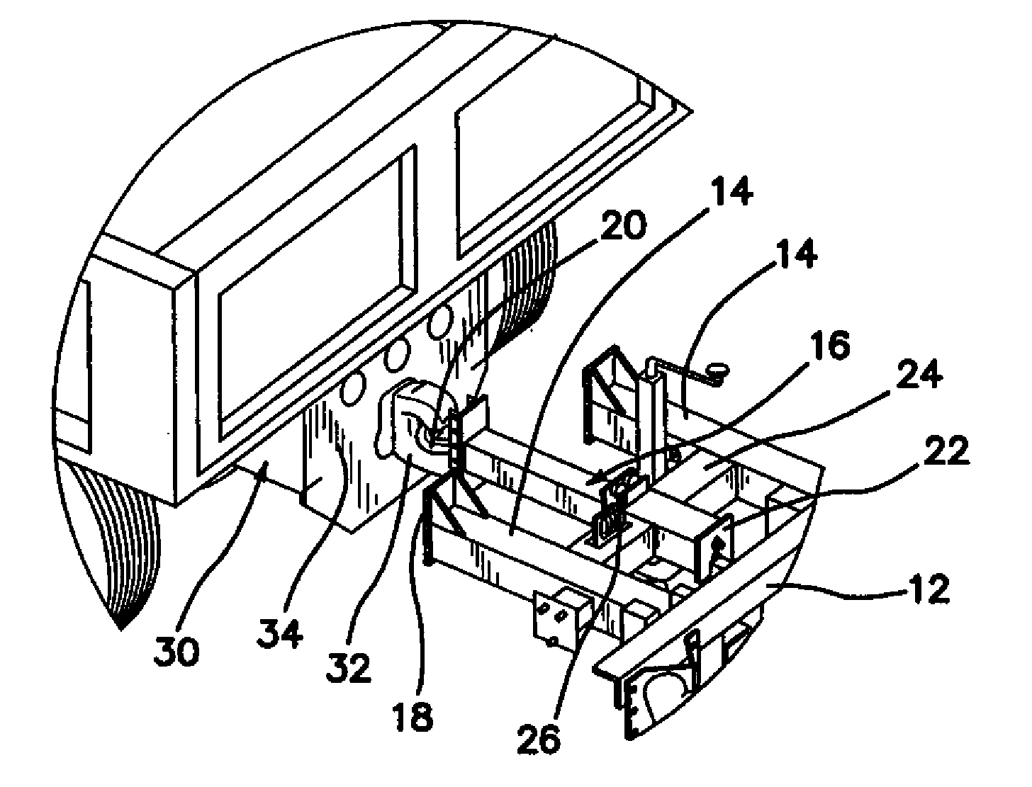
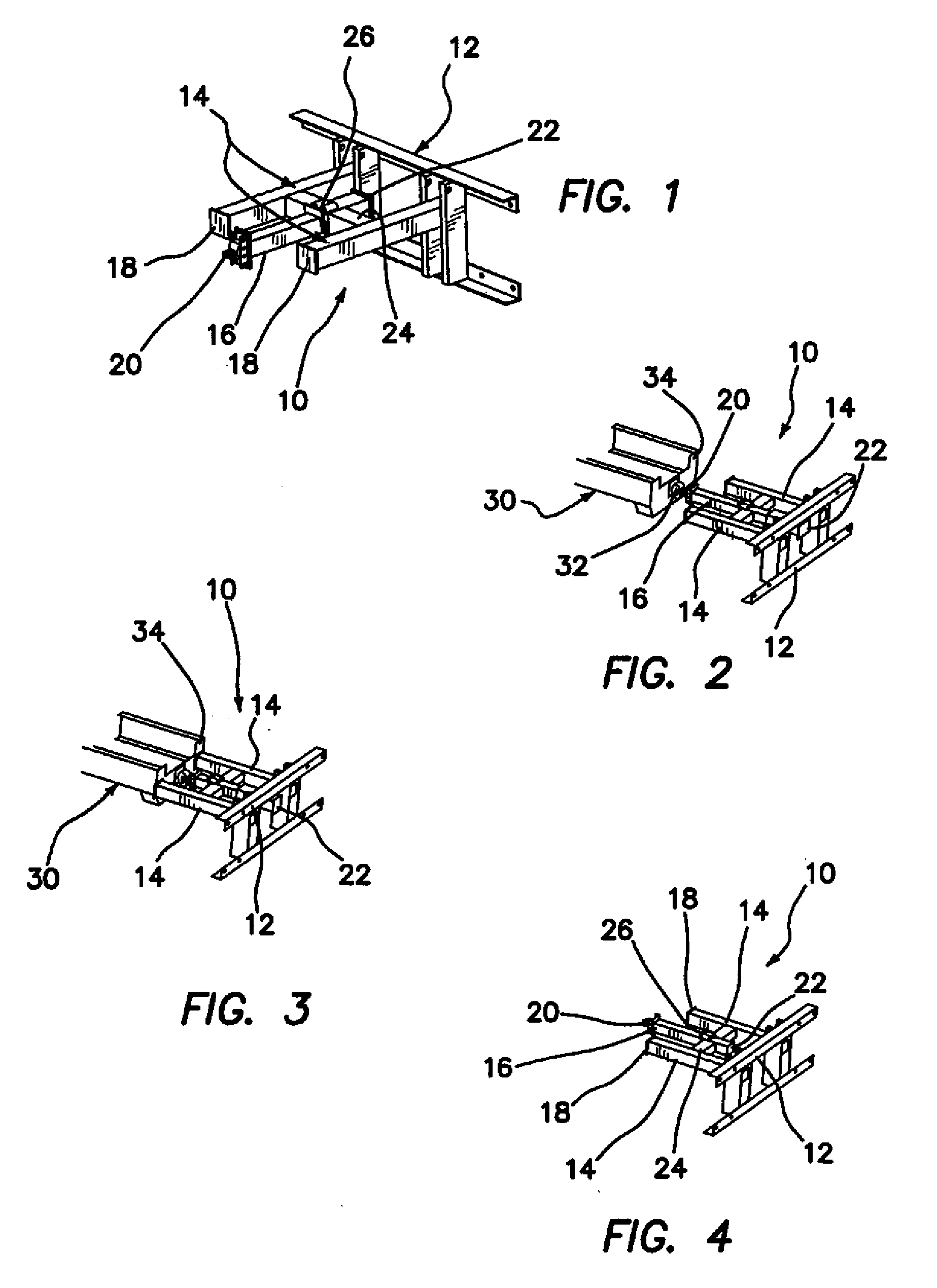
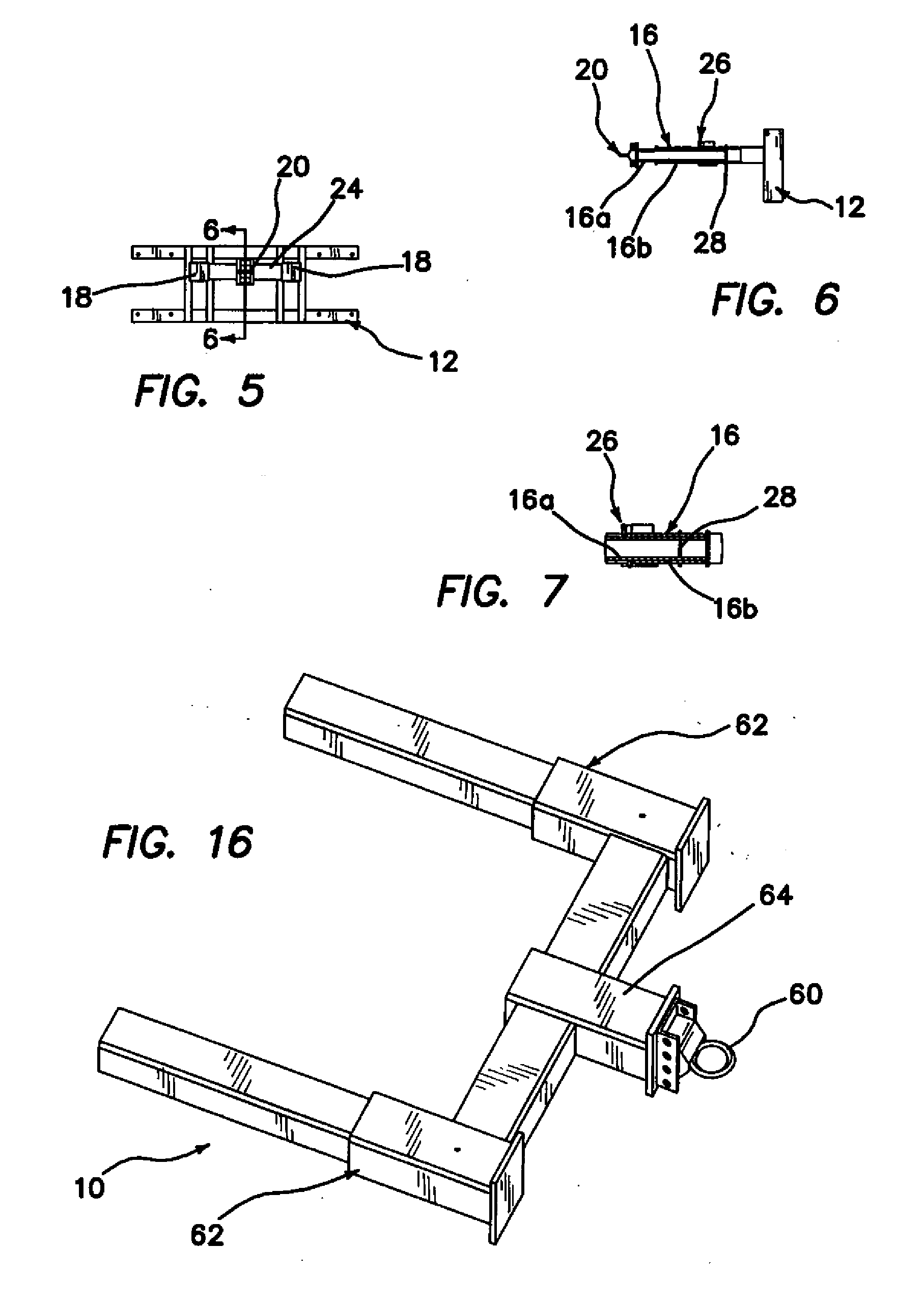
[0043]Referring now to the figures, wherein like reference numerals refer to like elements throughout the figures, there is shown in FIG. 1 a telescoping anti-rotation attachment system 10 constructed in accordance with the principles of the present invention. The system 10 comprises a backup frame 12, a pair of external anti-rotation support tubes 14, and an internal telescoping support tube 16.

[0044]Anti-rotation support pads 18 are disposed on the distal end of each of the external anti-rotation support tubes 14, and an adjustable eye assembly 20 is disposed on the distal end of the internal telescoping support tube 16.

[0045]The trailer attachment system 10, in a preferred embodiment, is made of A-36 steel and weights approximately 660 lbs. The overall dimensions are approximately 25 in.×54 3 / 16 in.×74 in. During normal operation, the system 10 attaches to a pintle hook on a truck, using the eye assembly 20, which in one embodiment comprises a 3 in. lunette eye. This eye is a sta...


PUM


Abstract

A trailer-mounted crash impact attenuator is disclosed for attachment to a host vehicle, which comprises an anti-rotational attachment system having an internal support tube and a plurality of external support tubes. The internal support tube has a connector on a front end thereof for attachment to a suitable receptacle on the host vehicle, and the plurality of external support tubes each have an anti-rotation support pad on a front end thereof. At least one of the internal support tube and the plurality of external support tubes is comprised of a telescoping construction. A backup frame is disposed on a rear end of the attachment system, and a crash attenuator unit is disposed on an axle and pair of wheels for mobility. When the crash attenuator is impacted by an errant vehicle, the anti-rotational attachment system is actuated to prevent the trailer mounted crash impact attenuator from rotating relative to the host vehicle.

Description

BACKGROUND OF THE INVENTION[0001]This application claims the benefit under 35 U.S.C. 119(e) of the filing date of Provisional U.S. Application Ser. No. 60 / 898,487, entitled Trailer Mounted Attenuator Telescoping Anti-Rotation System and filed on Jan. 30, 2007, which application is commonly assigned herewith and herein expressly incorporated herein by reference, in its entirety.[0002]1. Field of the Invention[0003]This invention relates to attenuators which are particularly adapted for the absorption of energy in the event of an impact between an errant vehicle and a second, typically stationary or slow-moving vehicle, in the hope of minimizing injury to the occupants of both vehicles, and, more specifically, to trailer-mounted crash attenuators.[0004]2. Description of the Related Art[0005]Truck mounted attenuators (TMA's) have been in use for many years. TMA's typically comprise a fixed backup mounted to a dump truck or other vehicle and an energy absorbing cartridge attached to the...

Claims


Application Information

Patent Timeline
Patent Type & Authority Applications(United States)
IPC IPC(8): B60R19/26
CPCB62D63/062B60R2019/005B62D21/152B60R19/34B60D1/50E01F9/0126B60R19/24B60D1/04E01F15/148B62D63/061B60D1/485B60D1/243E01F9/662G08G1/09
Inventor MAUS, GEOFFREY B.
Owner TRAFFIX DEVICES INC
Learn More