Synchronous machine and also method for manufacturing such a synchronous machine
- Summary
- Abstract
- Description
- Claims
- Application Information
AI Technical Summary
Benefits of technology
Problems solved by technology
Method used
Image
Examples
Embodiment Construction
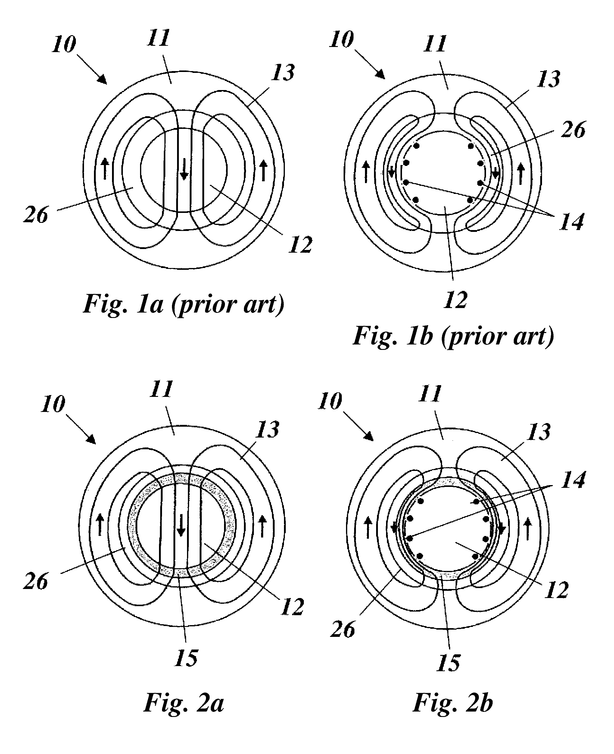
[0032]FIG. 2 represents the effect of the measure(s) according to principles of the invention in simplified form and in comparison to FIG. 1: The rotor 12 of the synchronous machine 10 is surrounded by a magnetizable casing 15 which reaches into the air gap 26 and preferably annularly surrounds the rotor12. In the case of steady operation without field harmonics and without non-symmetry (FIG. 2(a)), when no damper currents are induced, the stator magnetic field 13 of the stator 11 passes through the rotor 12 in the manner known from FIG. 1(a). In other cases of operation or incidents, damper currents 14 are induced (FIG. 2(b)) which urge the stator magnetic field 13 out of the rotor 12 and deflect it in the tangential direction (circumferential direction) predominantly through the magnetizable casing 15.
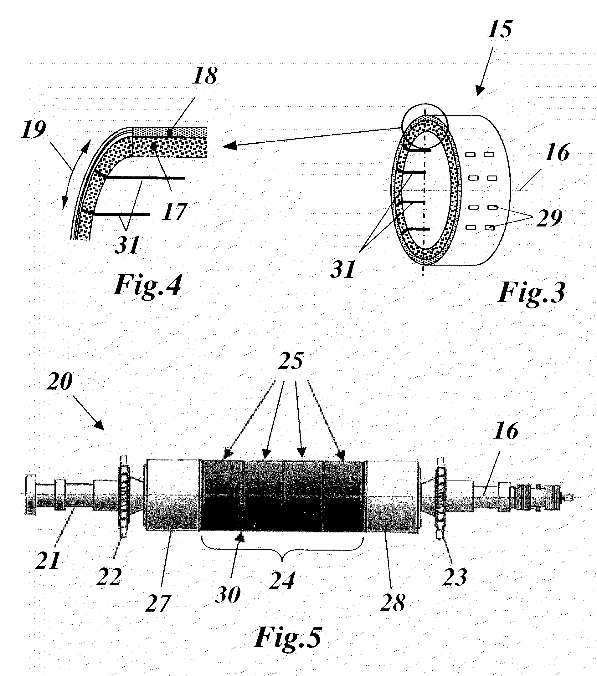
[0033]The magnetizable casing 15 is preferably made of what is known as a composite-shield material. Composite-shield materials are composite materials which are formed of fine iron ...
PUM
| Property | Measurement | Unit |
|---|---|---|
| Temperature | aaaaa | aaaaa |
| Pressure | aaaaa | aaaaa |
| Centrifugal force | aaaaa | aaaaa |
Abstract
Description
Claims
Application Information
 - R&D
- Intellectual Property
- Life Sciences
- Materials
- Tech Scout
- Unparalleled Data Quality
- Higher Quality Content
- 60% Fewer Hallucinations
Browse by: Latest US Patents, China's latest patents, Technical Efficacy Thesaurus, Application Domain, Technology Topic, Popular Technical Reports.
© 2025 PatSnap. All rights reserved.Legal|Privacy policy|Modern Slavery Act Transparency Statement|Sitemap|About US| Contact US: help@patsnap.com


