Cold Gas Spraying Method

a technology of gas spraying and cold gas, which is applied in the direction of pretreatment surfaces, pressure inorganic powder coatings, coatings, etc., can solve the problems of limited use of thermal spraying, and achieve the effects of reducing possible stresses in the coating, reducing structural stresses, and good adhesion

Inactive Publication Date: 2011-02-17
SIEMENS AG
View PDF10 Cites 9 Cited by
  • Summary
  • Abstract
  • Description
  • Claims
  • Application Information

AI Technical Summary

Benefits of technology

[0016]It can also be achieved by suitable selection of the nanoparticles that the different types of nanoparticles react with one another during the formation of the coating. By this means it is possible to produce precursors of reaction products as nanoparticles whose reaction products would pose problems during production as nanoparticles.
[0017]It can further be provided that the nanostructure of the coating will be selectively modified in a heat treatment step downstream of the coating process. By means of the heat treatment step diffusion processes of individual alloy elements of the nanoparticles or between nanoparticles of different composition can be set in train in the structure of the nanostructured coating, it being possible to selectively influence the structural modification through temperature and duration during the heat treatment. Furthermore the heat treatment can serve to reduce possible stresses in the coating.
[0018]It is also advantageous if additives for assisting the layer formation, in particular grain growth inhibitors, are contained in the particles in addition to the nanoparticles. By means of the grain growth inhibitors it is possible for example to obtain the nanostructure during a heat treatment of the nanostructured layer while at the same time reducing stresses in the structure. Grain growth inhibitors are described for example in U.S. Pat. No. 6,287,714 B1.
[0019]A favorable application of the method advantageously consists in the substrate being formed by a plastic body, in particular a lamp base, with a protective layer being embodied as the coating to protect against electromagnetic radiation in particular in the UV range, the composition of the protective layer being modified in the area adjacent to the lamp base in the interests of good adhesion on the lamp base. The lamp base requiring to be coated can be for example lamp bases of gas discharge lamps for use in automobile headlights. If the gas discharge lamp is in operation for a relatively long period of time the components of the headlight light in the UV range are namely detrimental to the lamp base which is manufactured from plastic and decomposes under the effect of said light. The necessity to coat the lamp base in order to protect against UV radiation can be learned for example from EP 1 460 675 A2. The problem that is to be solved in the case of the coating resides in the fact that the layers suitable as UV protection have a ceramic structural composition and consequently tend, due to their brittle characteristics, to flake off from the ductile parent material of the lamp base. This can be prevented through the inventive use of the described method on account of the fact that the composition of the layer at the lamp base is optimized in the interests of good adhesion. For example, a polymer component which simultaneously forms the microencapsulation can be incorporated as well into the layer so that the latter acquires properties which are comparable in terms of ductility with those of the parent material. At a later stage in the coating method a gradient layer can then be formed in which the proportion of polymer material toward the surface of the layer decreases and finally disappears completely, since this, being a LTV-light-sensitive component, must be kept away from the radiation of the lamp. The UV-light-tight components, copper oxide for example, can be provided as nanoparticles in the microencapsulation, with the proportion of nanoparticles of this type toward the layer surface being increased up to a proportion of 100%.

Problems solved by technology

The use of thermal spraying is limited to applications of this method on layer materials having a high temperature stability if the nanostructuring of the supplied nanoparticles is to remain intact (e.g. ceramic particles).

Method used


Image

  • Cold Gas Spraying Method
  • Cold Gas Spraying Method
  • Cold Gas Spraying Method

Examples


Embodiment Construction

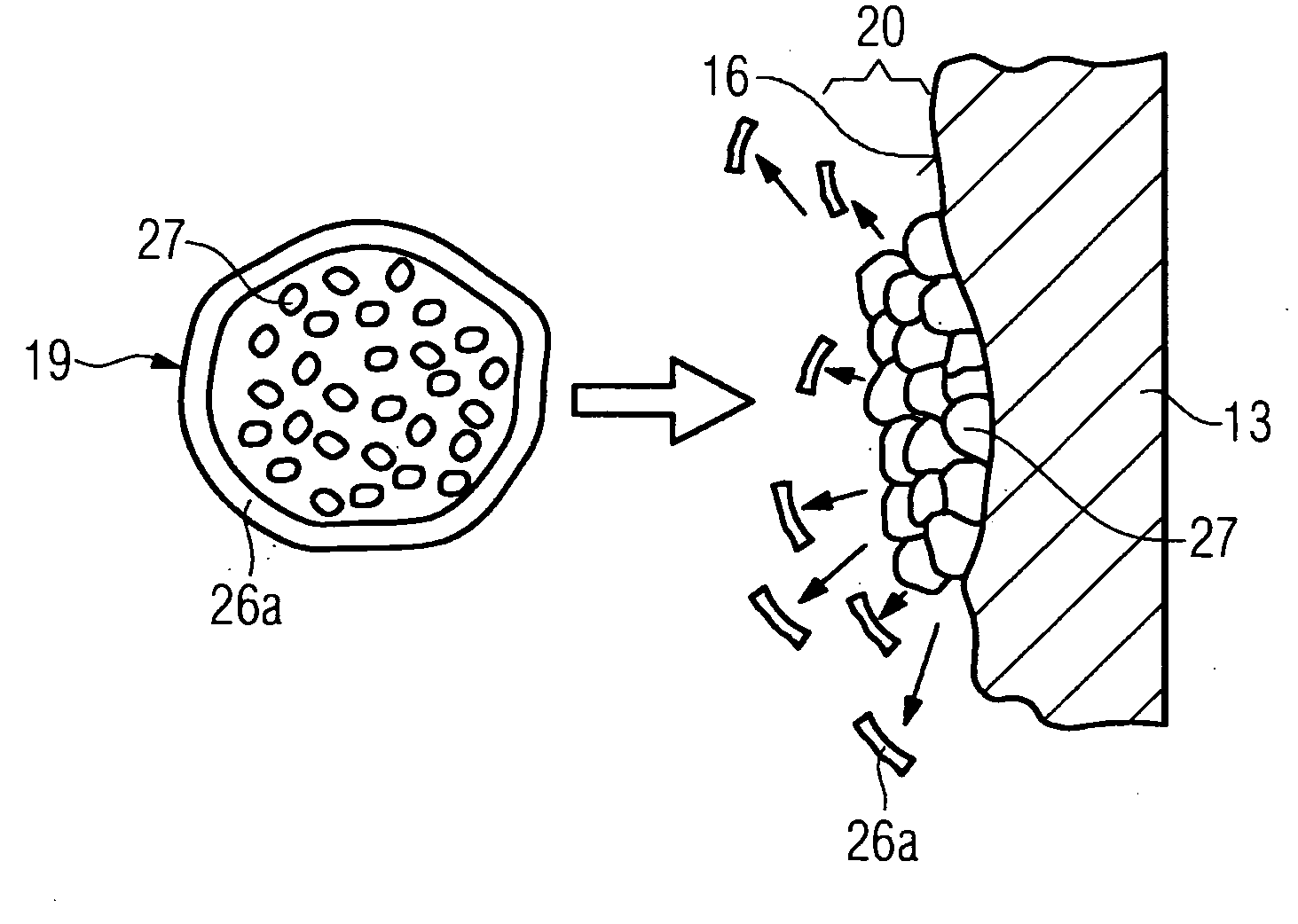
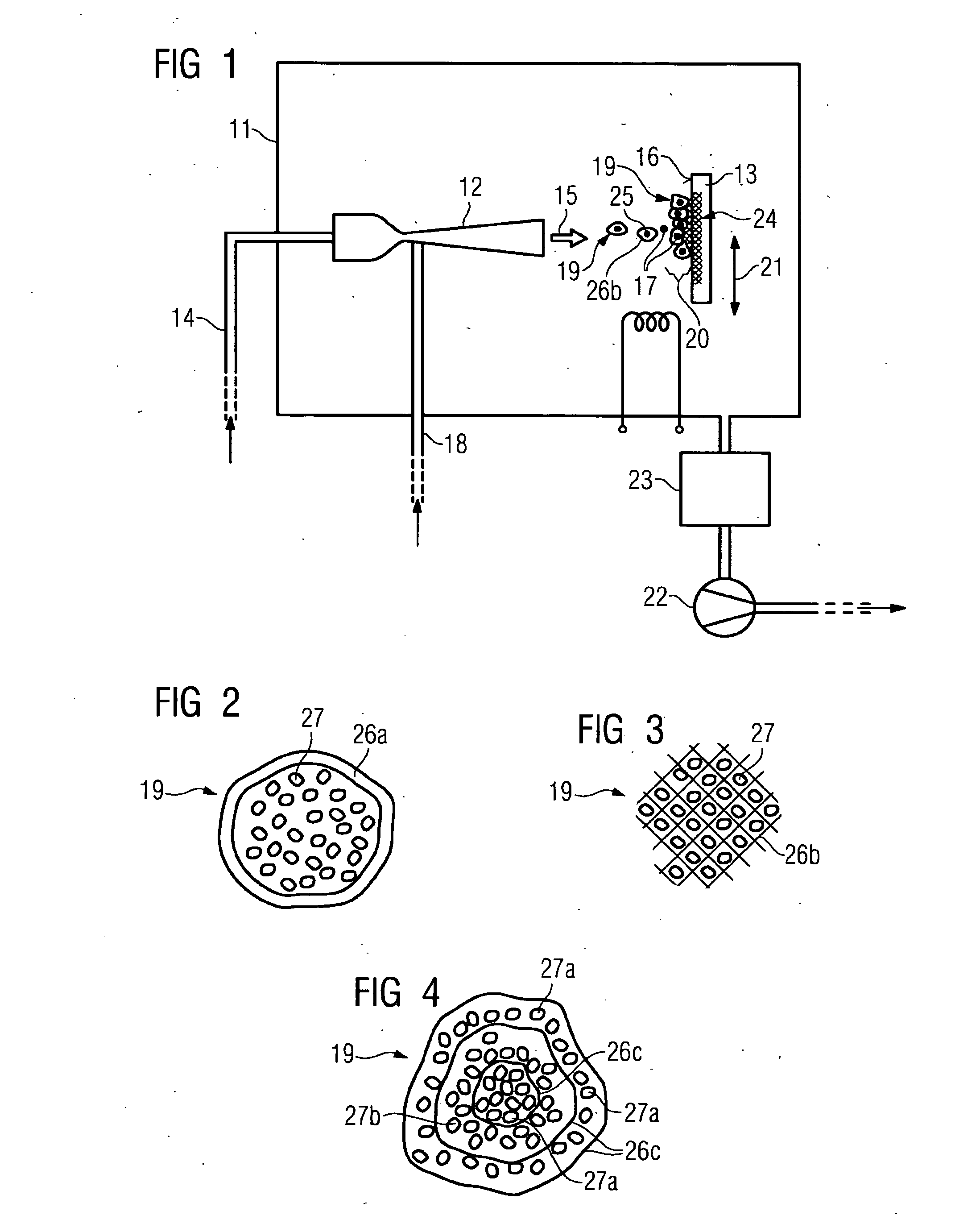
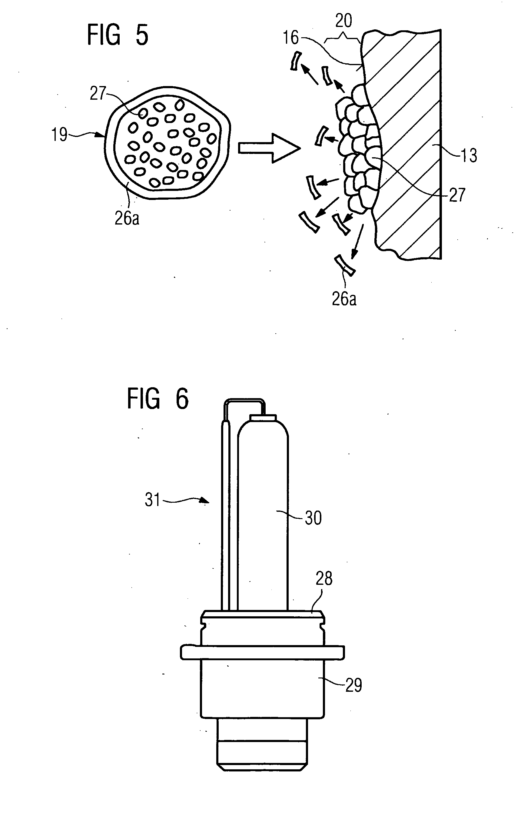
[0026]FIG. 1 shows a coating tool for cold gas spraying. This has a vacuum chamber 11 in which are disposed on the one hand a cold spray nozzle 12 and on the other hand a substrate 13 requiring to the coated (retaining fixture not shown in further detail). A process gas can be fed to the cold spray nozzle through a first line 14. As indicated by the contour, the cold spray nozzle has a Laval shape which causes the process gas to expand and be accelerated toward a surface 16 of the substrate 13 in the form of a cold gas jet (arrow 15). The process gas can contain oxygen 17, for example, as the reactive gas, which is involved in a reaction at the surface 16 of the substrate 13. The process gas can also be heated (not shown), as a result of which a required process temperature can be set in the vacuum chamber 11.

[0027]Particles 19 can be fed to the cold spray nozzle 12 through a second line 18, which particles 19 are accelerated in the gas jet and strike the surface 16. The kinetic ene...


PUM

PropertyMeasurementUnit
particle sizesaaaaaaaaaa
energyaaaaaaaaaa
adhesionaaaaaaaaaa

Abstract

The invention relates to a cold gas spraying method with the aid of which a substrate to be coated can be coated with particles. According to the invention, it is provided that microencapsulated agglomerates of nanoparticles are used as particles. This advantageously allows the advantages that accompany the use of nanoparticles to be used for the coating. The nanoparticles 271, 27b are held together by microencapsulations 26c, wherein the microencapsulated particles 19 formed in this way that are used in the cold gas spraying method have dimensions I the micrometer range, thereby allowing them to be used in the first place in cold gas spraying The microencapsulated nanoparticles may be used for example to produce a UV protective coating on lamp bases for gas discharge lamps.

Description

CROSS REFERENCE TO RELATED APPLICATIONS[0001]This application is the US National Stage of International Application No. PCT / EP2006 / 066392, filed Sep. 15, 2006 and claims the benefit thereof. The International Application claims the benefits of German application No. 10 2005 047 688.0 filed Sep. 23, 2005, both of the applications are incorporated by reference herein in their entirety.FIELD OF INVENTION[0002]The invention relates to a cold gas spraying method, wherein a cold gas jet that is directed at a substrate requiring to be coated and to which particles forming the coating are added is generated by means of a cold spray nozzle.BACKGROUND OF THE INVENTION[0003]The cold gas spraying method referred to above is known for example from DE 102 24 780 A1, wherein particles that are intended to form a coating on a substrate requiring to be coated are injected into a cold gas jet generated by means of a cold spray nozzle and accelerated by means of the latter preferably to supersonic spe...

Claims


Application Information

Patent Timeline
Patent Type & Authority Applications(United States)
IPC IPC(8): B05D1/12
CPCC23C24/04
Inventor JABADO, RENEJENSEN, JENS DAHLKRUGER, URSUSKORTVELYESSY, DANIELLUTHEN, VOLKMARPYRITZ, UWEREICHE, RALPHRINDLER, MICHAELULLRICH, RAYMOND
Owner SIEMENS AG
Why Eureka
Try Eureka