Electronically scanned radar system

a radar system and electromagnetic technology, applied in the field of electromagnetic scanning radar system, can solve problems such as deterioration in measurement accuracy, and achieve the effects of suppressing the influence of interference wav

Active Publication Date: 2010-01-28
DENSO CORP
View PDF3 Cites 59 Cited by
  • Summary
  • Abstract
  • Description
  • Claims
  • Application Information

AI Technical Summary

Benefits of technology

[0029]According to the invention of claim 1, the sampled data obtained after performing sampling is made into at least two or more continuous cut-out data. Thus, a beat signal can be captured as temporally transited information, that is, information of at least two or more timings. Thus, frequency variation of an interference wave in the interference frequency components, relative to time can be estimated. Further, when the estimated interference component frequency is removed by the interference component removal part, the influence of the interference wave can be suppressed.
[0030]In the invention of claim 2, M is set so that the frequency is substantially unchanged in the M number of sampled data. Thus, the cut-out sampled data substantially has no frequency variation in the interference frequency components, relative to time, which variation can be seen after sampling. Accordingly, the beat frequency of the interference components can be more properly detected in the time segment.
[0031]In the invention of claim 3, removal of the interference frequency is ensured to be performed by having the interference component removal part removing the beat signal in a portion where the beat signal corresponding to the reception wave intersects with the beat signal corresponding to the interference wave. For example, when a transmission wave of an own vehicle is reflected by a target, the beat signal of the reflected wave is a signal which does not transit with respect to time, wh

Problems solved by technology

The interference signal of a large electrical power level can be

Method used


Image

  • Electronically scanned radar system
  • Electronically scanned radar system
  • Electronically scanned radar system

Examples


first embodiment

[0063]With reference to the drawings, hereinafter will be described the present invention.

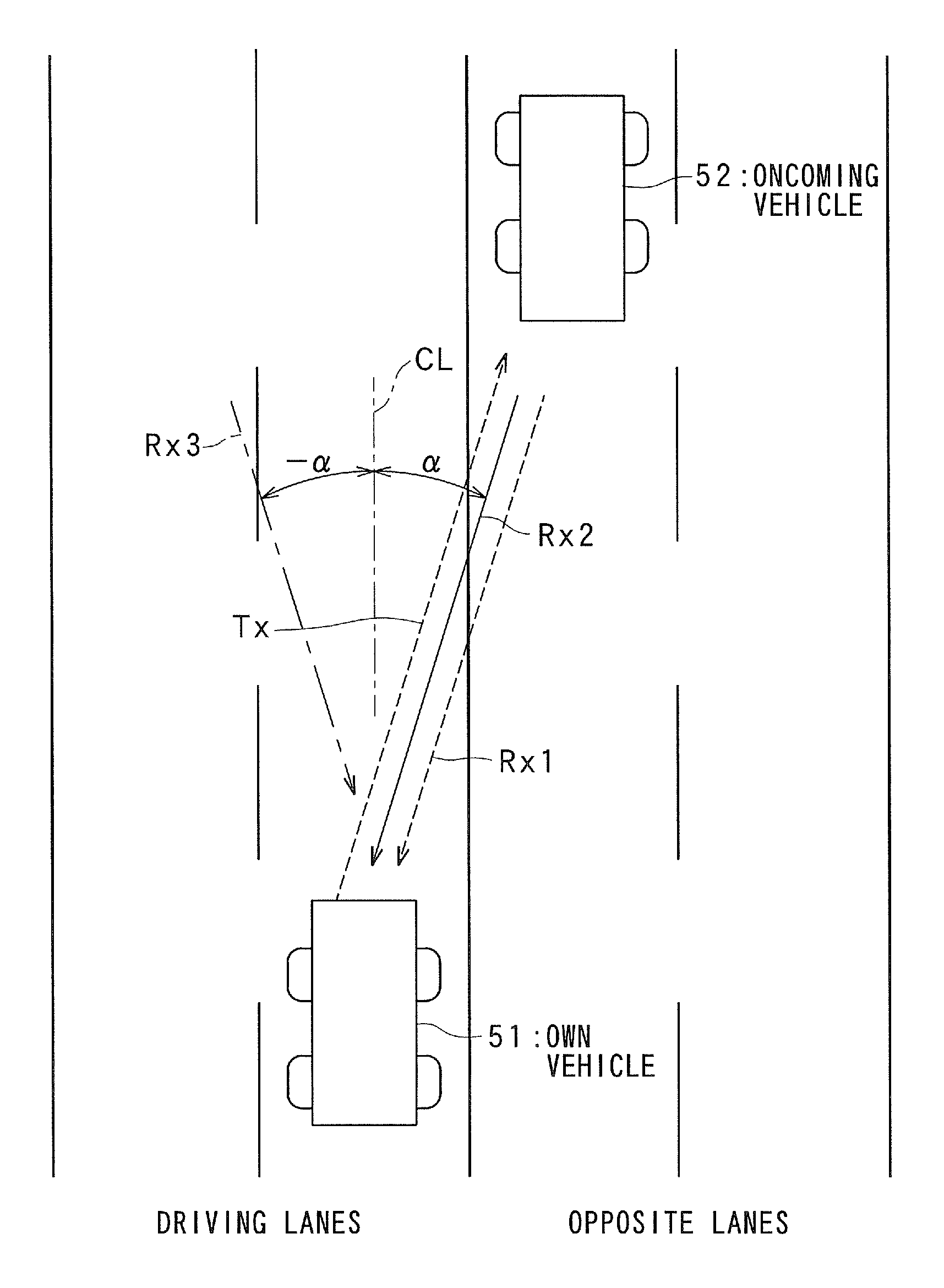
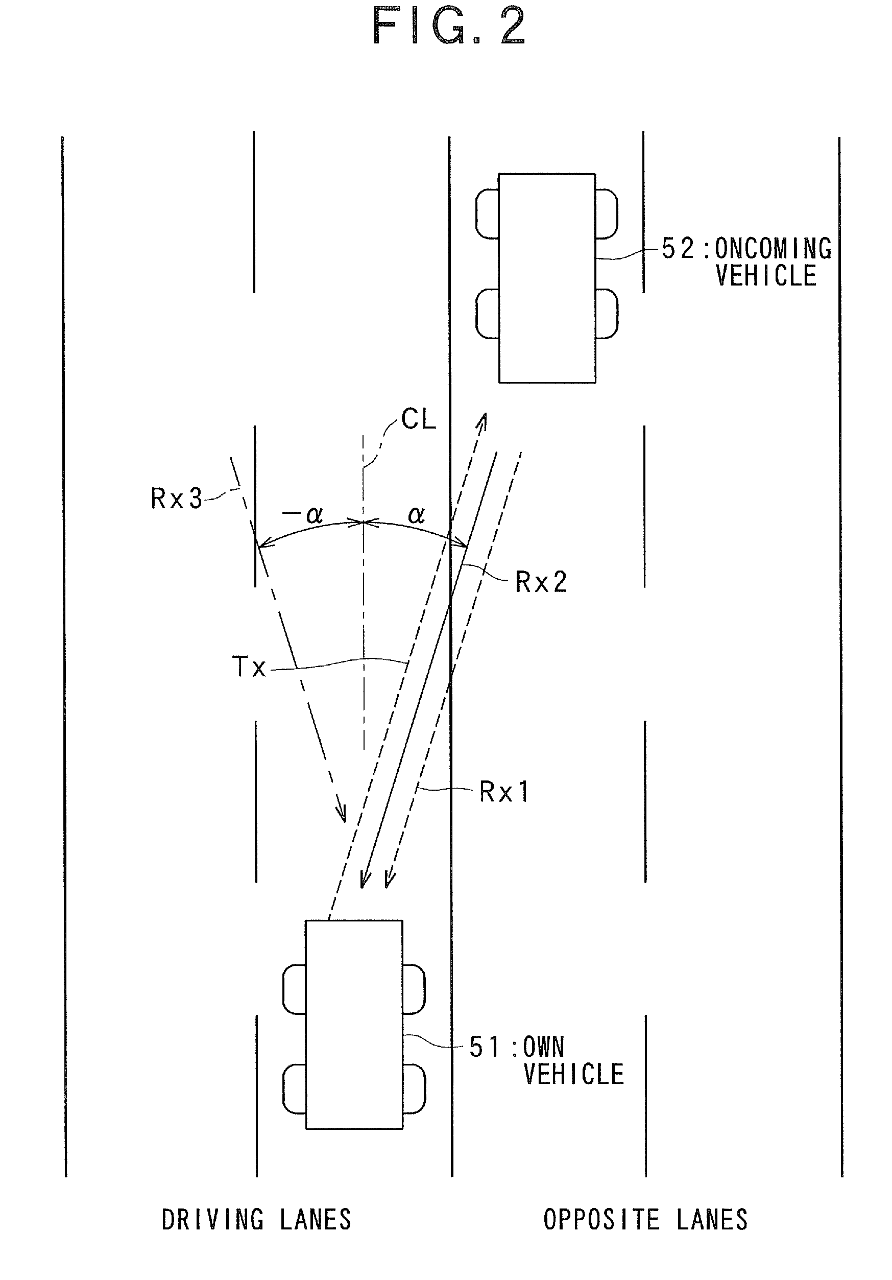
[0064]FIG. 4 is a block diagram illustrating an electronically scanned radar system 1 according to an embodiment of the present invention. The radar system 1 is an FM-CW radar system using a transmission signal Tx which is obtained by applying frequency modulation (FM) to a continuous wave (CW). Also, the radar system 1 is a DBF radar system which performs digital beam forming processes within receiving array antennas 8. The radar system 1 is a so-called on-vehicle radar system loaded on a vehicle, which detects, for example, a distance to a vehicle (target) traveling ahead or a relative speed of the vehicle traveling ahead. The results of the detection of the radar system 1 are utilized, for example, as information for controlling traveling of the vehicle. Microwaves are used as transmission waves,

[0065]The radar system 1 has a transmission / reception section 4 which includes: an oscillator 2 h...

second embodiment

[0103]Referring to FIG. 10, hereinafter is described a

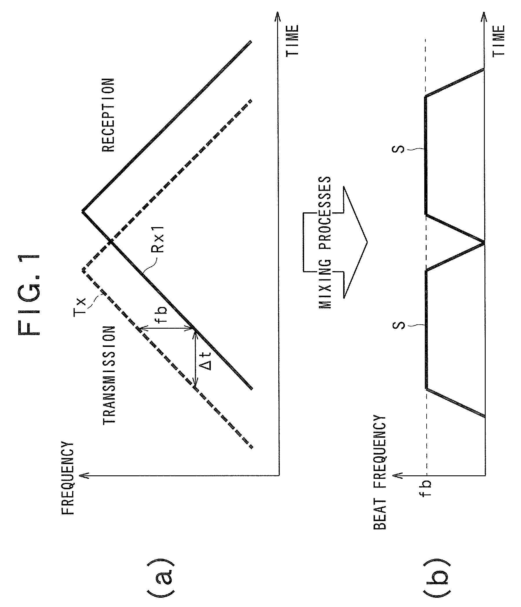
[0104]Since (a) and (b) of FIG. 10 are substantially the same as FIG. 3, the explanation is simplified.

[0105]The second embodiment greatly differs from the above embodiment and modification in that no DBF function is provided. In the second embodiment, removal using the projection matrix, for example, is performed for two intersections between the beat signal S corresponding to the reflected wave Rx1 and the beat signal corresponding to the interference wave Rx2 after being mixing by a mixer. Specifically, both the beat signal S and the beat signal of the interference wave Rx2 are removed from the interference frequency at the intersections mentioned above or during the periods including the intersections, and in all else, only the beat signal of the reference wave Rx2 is removed. More specifically, as shown by (d) of FIG. 10, the intersections mentioned above reside at the time points To4 and To1. Thus, both the beat signal S an...


PUM


Abstract

A sampled beat signal RD is split into a plurality of short-time data SD in the time direction, for each of antenna elements. Interference component frequency of an interference wave is detected from a frequency spectrum of the short-time data SD. A digital beam forming process is performed for the interference component frequency of the interference wave to extract a peak of the electrical power of an azimuth direction and estimate an absolute value of an incoming direction of interference components. Based on the absolute value of the incoming direction of the estimated interference components, a filter for suppressing the interference components is operated to suppress the interference components.

Description

TECHNICAL FIELD[0001]The present invention relates to an electronically scanned radar system, and in particular to an on-vehicle electronically scanned radar system using the FM-CW technique, which is able to suppress interference signals contained in received signals.BACKGROUND ART[0002]FIG. 1 shows timing diagrams indicating transmitted / received signals and the principle of mixing processes in the FM-CM radar technique. FIG. 2 is a plan view illustrating an example of an environment of a road with opposite lanes. FIG. 3 shows by (a) and (b) conditions of signal processing in a radar system equipped in a vehicle in the case where an interference signal has been received from another vehicle.[0003]In order to prevent collisions between vehicles and to perform inter-vehicle control, on-vehicle radars have been developed, which measure a distance, speed and azimuth associated with a front target, such as a preceding vehicle.[0004]As a means for measuring a distance from a front target...

Claims


Application Information

Patent Timeline
IPC IPC(8): G01S13/34G01S7/02
CPCG01S7/023G01S7/2813G01S7/352G01S2007/356G01S13/42G01S13/931G01S13/345G01S7/356
Inventor YAMANO, CHIHARUNATSUME, KAZUMAWATANABE, YUUSAKAMOTO, MAI
Owner DENSO CORP
Why Eureka
Try Eureka