Optically enhanced flat panel display system having integral touch screen

a touch screen and display system technology, applied in the field can solve the problems of flat panel display systems that suffer from luminance loss, flat panel display systems that are more expensive to manufacture, and not always perform well, so as to improve the net luminance, reduce reflectance, and increase luminance

Inactive Publication Date: 2010-01-28
L 3 COMM CORP
View PDF9 Cites 14 Cited by
  • Summary
  • Abstract
  • Description
  • Claims
  • Application Information

AI Technical Summary

Benefits of technology

[0006]Broadly described, the present invention comprises an optically enhanced flat panel display system, including apparatuses and methods, for displaying images generated by a computer or electronic device with increased luminance and reduced reflectance, and for receiving user input for a computer or electronic device via a touch screen portion thereof. More particularly, the present invention comprises a flat panel display system having a touch screen portion integrally incorporated with and forward of a display portion. The flat panel display system has only one front polarizer such that the touch screen and display portions are positioned rearward thereof. Because the flat panel display system of the present invention has only a single front polarizer, the display system's net luminance is improved over prior art devices having multiple front polarizers that tend to attenuate light passing therethrough. Also, such improvement in net luminance is achieved without reducing the display system's contrast or color performance.

Problems solved by technology

Unfortunately, such flat panel display systems do not always perform well when direct sunlight impinges upon them as may happen during an aircraft's flight.
Such flat panel display systems also tend to require complex hardware and / or software, making them more expensive to manufacture.
Unfortunately, such flat panel display systems suffer from a loss of luminance due to excess light filtering caused by the presence of redundant polarizers in the AMLCDs and resistive touch screens.

Method used


Image

  • Optically enhanced flat panel display system having integral touch screen
  • Optically enhanced flat panel display system having integral touch screen
  • Optically enhanced flat panel display system having integral touch screen

Examples


Embodiment Construction

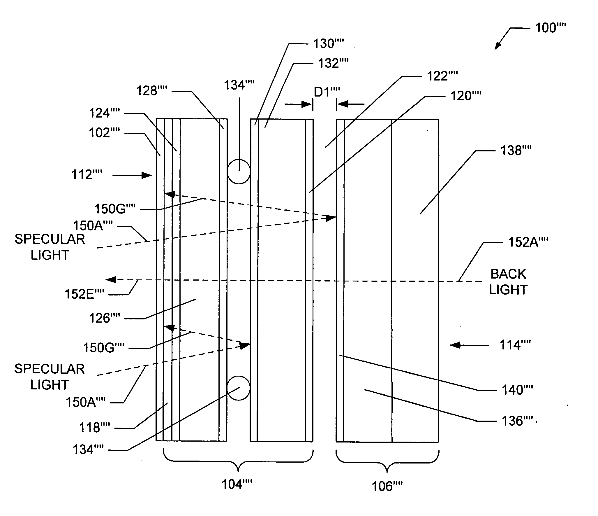
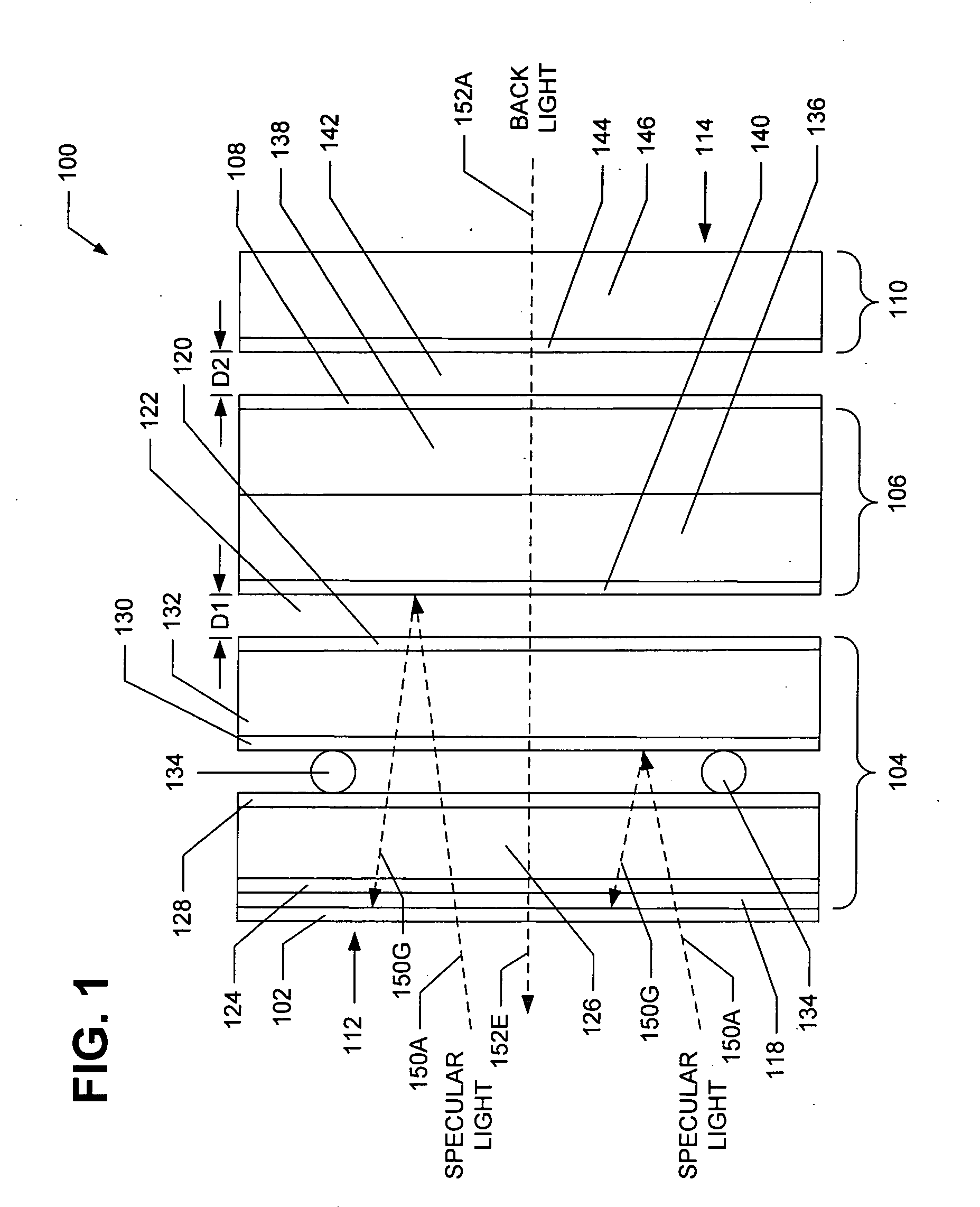
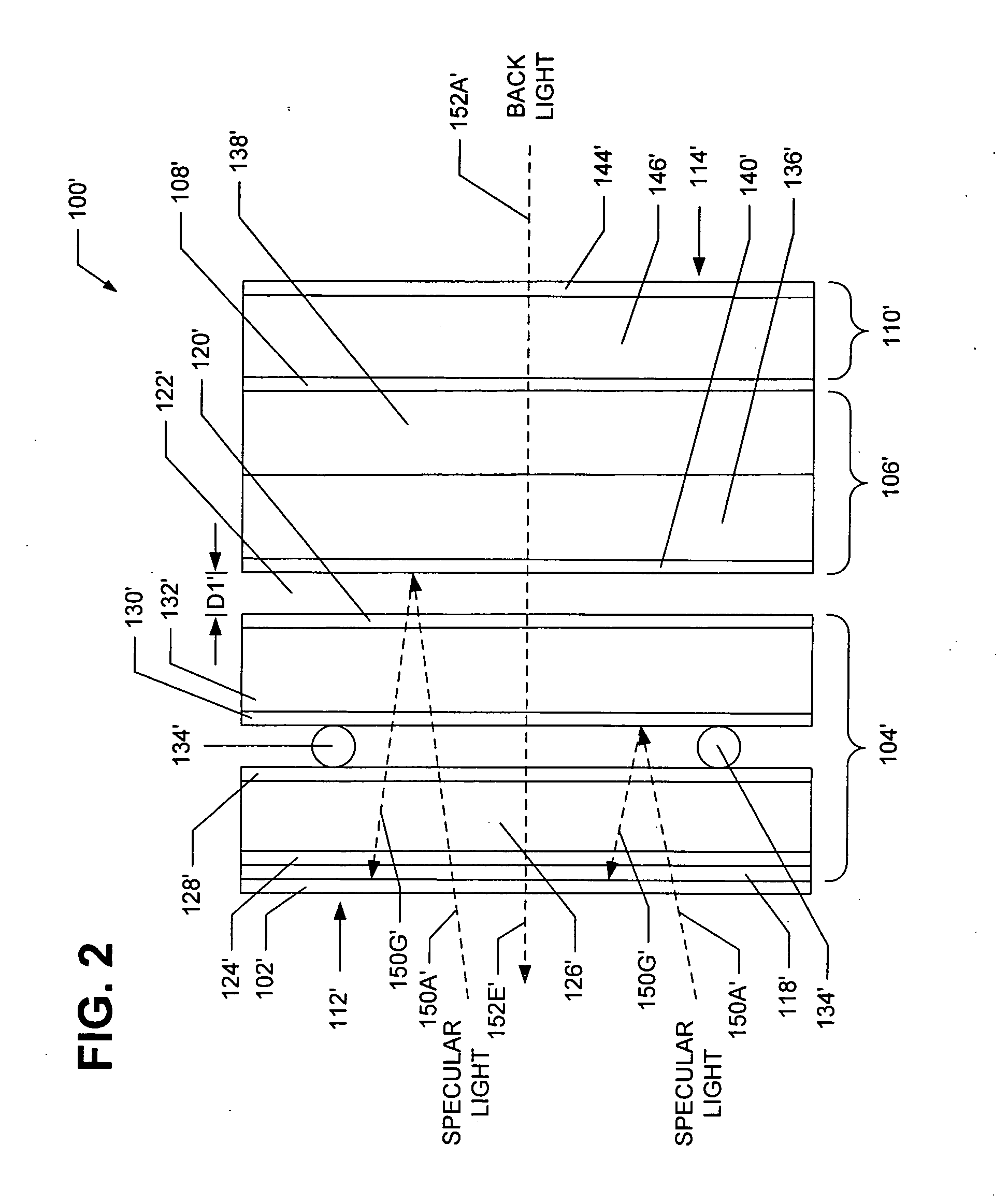
[0016]Referring now to the drawings in which like numerals represent like elements or steps throughout the several views, FIG. 1 displays a side view of a flat panel display system 100 in accordance with a first exemplary embodiment of the present invention. The flat panel display system 100 comprises a single front polarizer 102, a resistive touch screen portion 104, an AMLCD portion 106, a single rear polarizer 108, and an AMLCD heater portion 110 that are arranged as layers in a substantially sandwich-like structure. The flat panel display system 100 has a front 112 and back 114 with the front polarizer 102, the resistive touch screen portion 104, the AMLCD portion 106, the rear polarizer 108, and the AMLCD heater portion 110 being sequentially and substantially adjacently arranged between the display system's front 112 and back 114. The flat panel display system 100 is adapted to receive light, during operation, from a light source (not shown) that is located proximate the back ...


PUM


Abstract

An optically enhanced flat panel display system, including apparatuses and methods for assembling same, for displaying images generated by a computer or electronic device with increased luminance and reduced reflectance, and for receiving user input for a computer or electronic device via a touch screen portion thereof. The flat panel display system comprises a touch screen portion integrally incorporated with and forward of a display portion. The display system has only one front polarizer such that the touch screen and display portions are generally positioned rearward thereof. In exemplary embodiments, the touch screen portion employs resistive touch screen technology and the display portion employs liquid crystal display technology. By including only one front polarizer, attenuation of display image light is minimized and an increase in net luminance is achieved over other flat panel display systems.

Description

FIELD OF THE INVENTION[0001]The present invention relates generally to the field of flat panel display systems and more specifically to liquid crystal displays employed in connection with touch screens.BACKGROUND OF THE INVENTION[0002]Since their initial development, flat panel display systems with active matrix liquid crystal displays (“AMLCDs”) have become increasingly popular for the display of computer-generated data in residential, commercial, and military environments. To enable user interaction with the computers that generate such data, manufacturers have coupled AMLCDs with touch screens that allow users to select a displayed item or otherwise provide an input to the computers by merely touching a user-accessible front cover panel of the touch screens.[0003]For example, some flat panel display systems that are employed in the cockpits of certain military aircraft have AMLCDs equipped with touch screens based on infrared touch technology. Using such a flat panel display syst...

Claims


Application Information

Patent Timeline
Patent Type & Authority Applications(United States)
IPC IPC(8): G09G3/36G06F3/042
CPCG06F3/0421G06F3/0412
Inventor WALSH, KEVINFLETCHER, MARK
Owner L 3 COMM CORP
Why Eureka
Try Eureka