Magnetic resonance imaging apparatus

a magnetic resonance imaging and apparatus technology, applied in the field of magnetic resonance imaging, can solve the problems of difficult application of parallel imaging methods, inability to fully cope with a lowering of s/n ratio, and signal defect, and achieve the effect of high diagnostic image quality

Inactive Publication Date: 2010-01-28
GE MEDICAL SYST GLOBAL TECH CO LLC
View PDF0 Cites 11 Cited by
  • Summary
  • Abstract
  • Description
  • Claims
  • Application Information

AI Technical Summary

Benefits of technology

[0021]According to the magnetic resonance imaging apparatus of the present invention, even if magnetic resonance signals are collected using plural receiving coils and in multiple channels, it is possible to attain a high quality of a diagnostic image.

Problems solved by technology

Since coaxial cables are used for the transmission of signals from the probe coils to the data collector, there is a fear that there may occur a signal defect due to the inclusion of an electromagnetic noise, with consequent disturbance of an image displayed on a display of an operating unit.
Heretofore, however, there sometimes has occurred a case where the application of the parallel imaging method is difficult due to the inclusion of noise into coaxial cables, or it is impossible to fully cope with a lowering of S / N ratio which basically occurs with an increase of the radiographing speed.
Thus, there also has occurred a problem such that the case to which the parallel imaging method is applicable is actually limited.
In case of collecting magnetic resonance signals through multiple channels in the application of the parallel imaging method, there is a fear of occurrence of crosstalk between signals being transmitted through coaxial cables of the channels.

Method used


Image

  • Magnetic resonance imaging apparatus
  • Magnetic resonance imaging apparatus
  • Magnetic resonance imaging apparatus

Examples


Embodiment Construction

[0027]An embodiment of the present invention will be described hereinunder with reference to FIGS. 1 to 4.

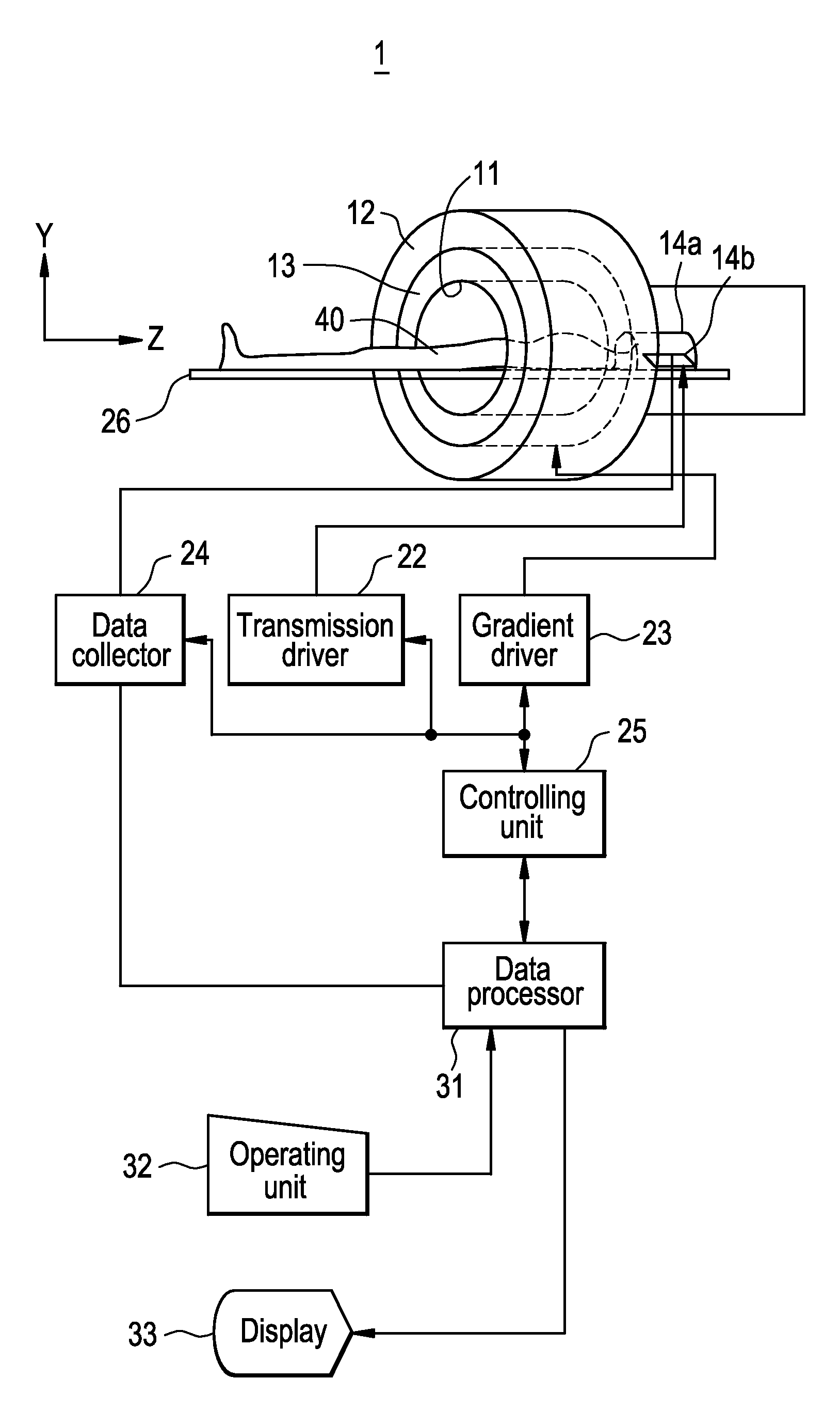
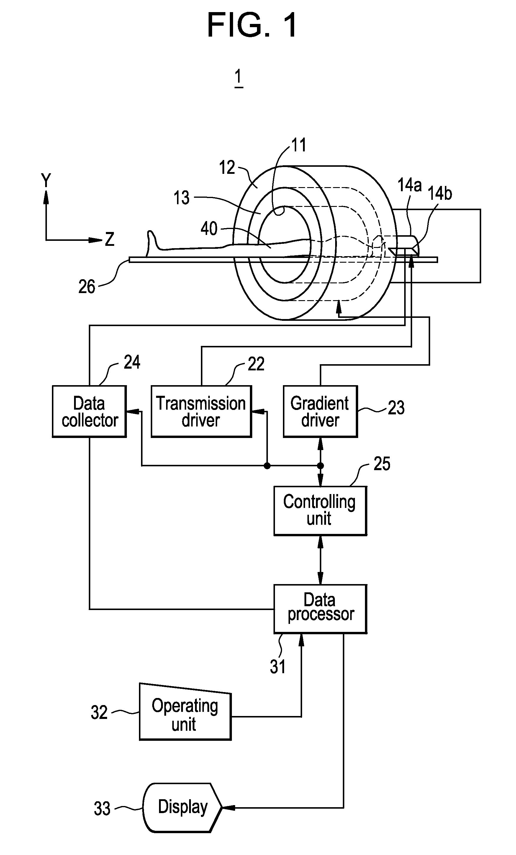
[0028]A magnetic resonance imaging apparatus 1 shown in FIG. 1 includes a static magnetic field-forming magnet unit 12, a gradient coil unit 13, a transmitting coil unit 14a, a receiving coil unit 14b, a transmission driver 22, a gradient driver 23, a data collector 24, a controlling unit 25, a cradle 26, a data processor 31, an operating unit 32, and a display 33.

[0029]The static magnetic field-forming magnet unit 12 and the gradient coil unit 13 are disposed around a bore 11 which is a columnar radiographing space. The transmitting coil unit 14a and the receiving coil unit 14b are disposed for example in the head, i.e., a radiographing area, of a subject 40 and, when radiographing the subject, are moved into the bore 11 together with the radiographing area of the subject 40.

[0030]Each of the components will be described below one by one.

[0031]The static magnetic field-forming ...


PUM


Abstract

With a view to attaining a high quality of a diagnostic image there is provided a magnetic resonance imaging apparatus wherein an image is formed on the basis of magnetic resonance signals received from a subject with an electromagnetic wave transmitted thereto in a static magnetic field. The magnetic resonance imaging apparatus is provided with plural receiving coil units for receiving the magnetic resonance signals, the receiving coil units each comprising a coil body configured to receive a corresponding one of the magnetic resonance signals and output an electrical signal and an optical modulator configured to use an electric field of the electric signal outputted from the coil body directly as a modulation signal.

Description

BACKGROUND OF THE INVENTION[0001]The present invention relates to a magnetic resonance imaging (MRI: Magnetic Resonance Imaging) apparatus. Particularly, the present invention is concerned with a magnetic resonance imaging apparatus of the type in which magnetic resonance signals are collected using plural receiving coils and multiple channels.[0002]Imaging apparatuses, e.g., a magnetic resonance imaging apparatus, are known apparatuses for radiographing a slice image of a tomographic face of a subject and are used in various fields, including medical and industrial fields.[0003]For example, when radiographing a slice image with use of a magnetic resonance imaging apparatus, first a subject is accommodated within a space with a static magnetic field formed therein and the direction of spin of protons present within the subject as a living body is regulated to the direction of the static magnetic field, affording a state of a magnetization vector having been obtained. Thereafter, an ...

Claims


Application Information

Patent Timeline
Patent Type & Authority Applications(United States)
IPC IPC(8): A61B5/055
CPCG01R33/3415G01R33/5611G01R33/3692
Inventor FUKUCHI, HARUYUKI
Owner GE MEDICAL SYST GLOBAL TECH CO LLC
Why Eureka
Try Eureka