Hydrodynamic Thrombectomy Catheter

a catheter and hydrodynamic technology, applied in the field of hydrodynamic thrombectomy catheter devices, can solve the problems of reducing the blood carrying capacity of the vessel, serious and permanent injury, or even death, and relatively large catheter profiles

Inactive Publication Date: 2010-01-28
MEDTRONIC VASCULAR INC
View PDF8 Cites 62 Cited by
  • Summary
  • Abstract
  • Description
  • Claims
  • Application Information

AI Technical Summary

Problems solved by technology

Human blood vessels may become occluded or completely blocked by thrombi (blood clots), which reduce the blood carrying capacity of the vessel.
If the blockage occurs at a critical place in the circulatory system, serious and permanent injury, or even death, can occur.
The drive shaft component results in a relatively large profile catheter, which may be stiffer and less flexible with limited applicability.
For example, such thrombectomy devices may not be used for removing blood clots from the intracranial circulation since the blood vessels in the brain are very small and tortuous.
In addition, the motors of these devices may be susceptible to stalling out due to friction loss when the catheter is snaked through a tortuous vessel.

Method used


Image

  • Hydrodynamic Thrombectomy Catheter
  • Hydrodynamic Thrombectomy Catheter
  • Hydrodynamic Thrombectomy Catheter

Examples


Embodiment Construction

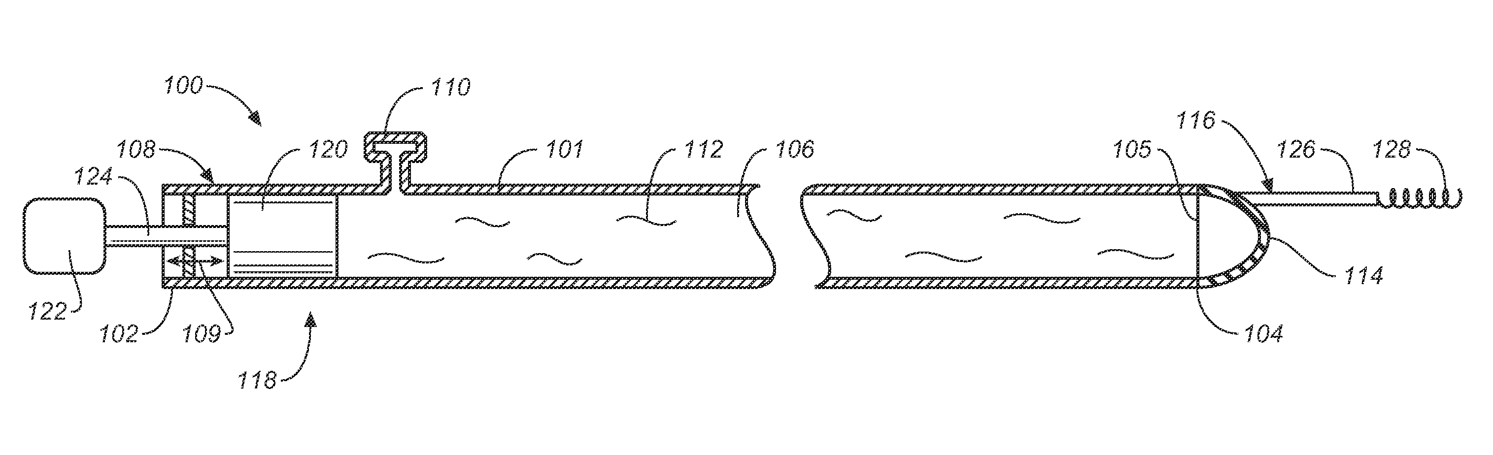
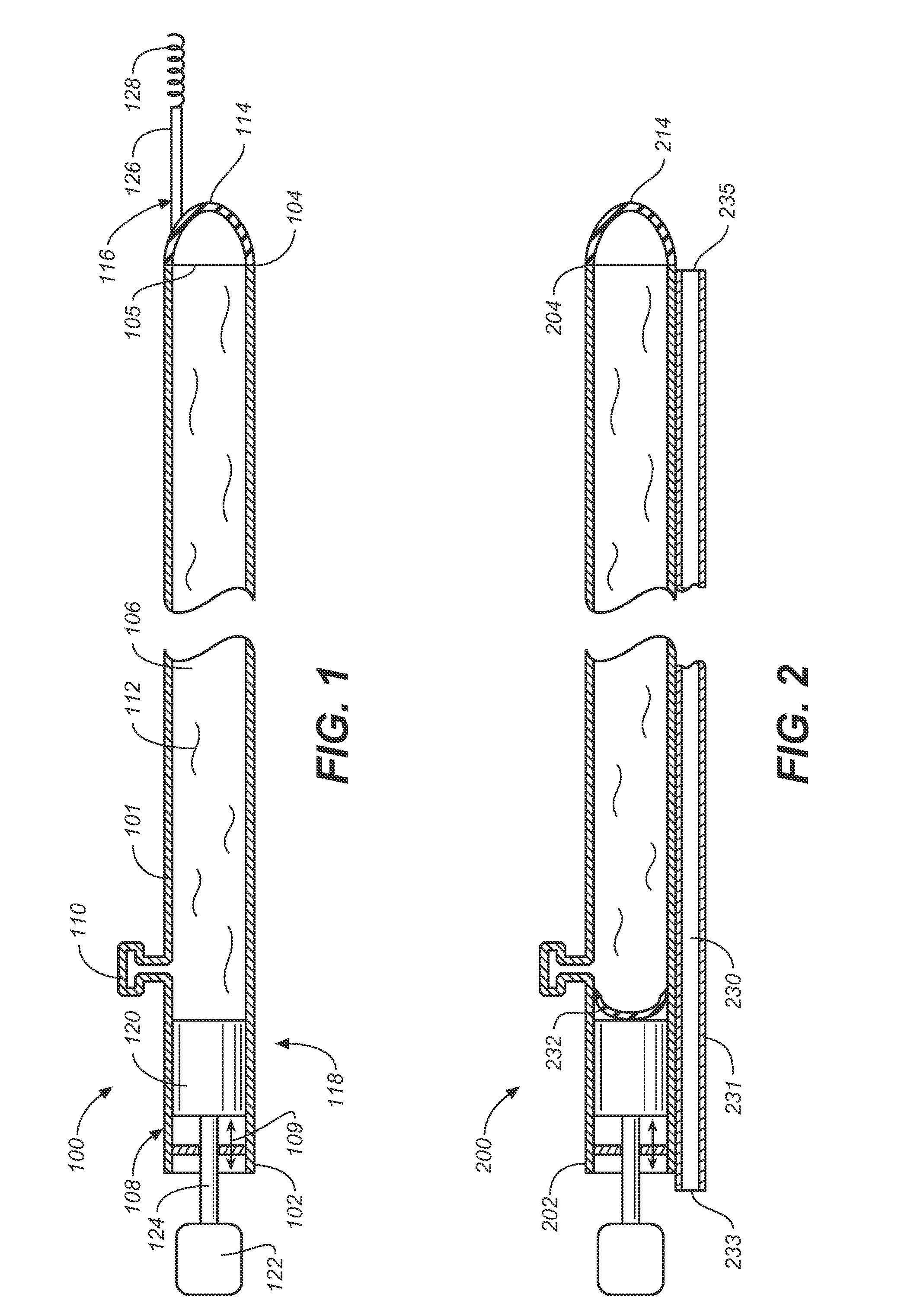
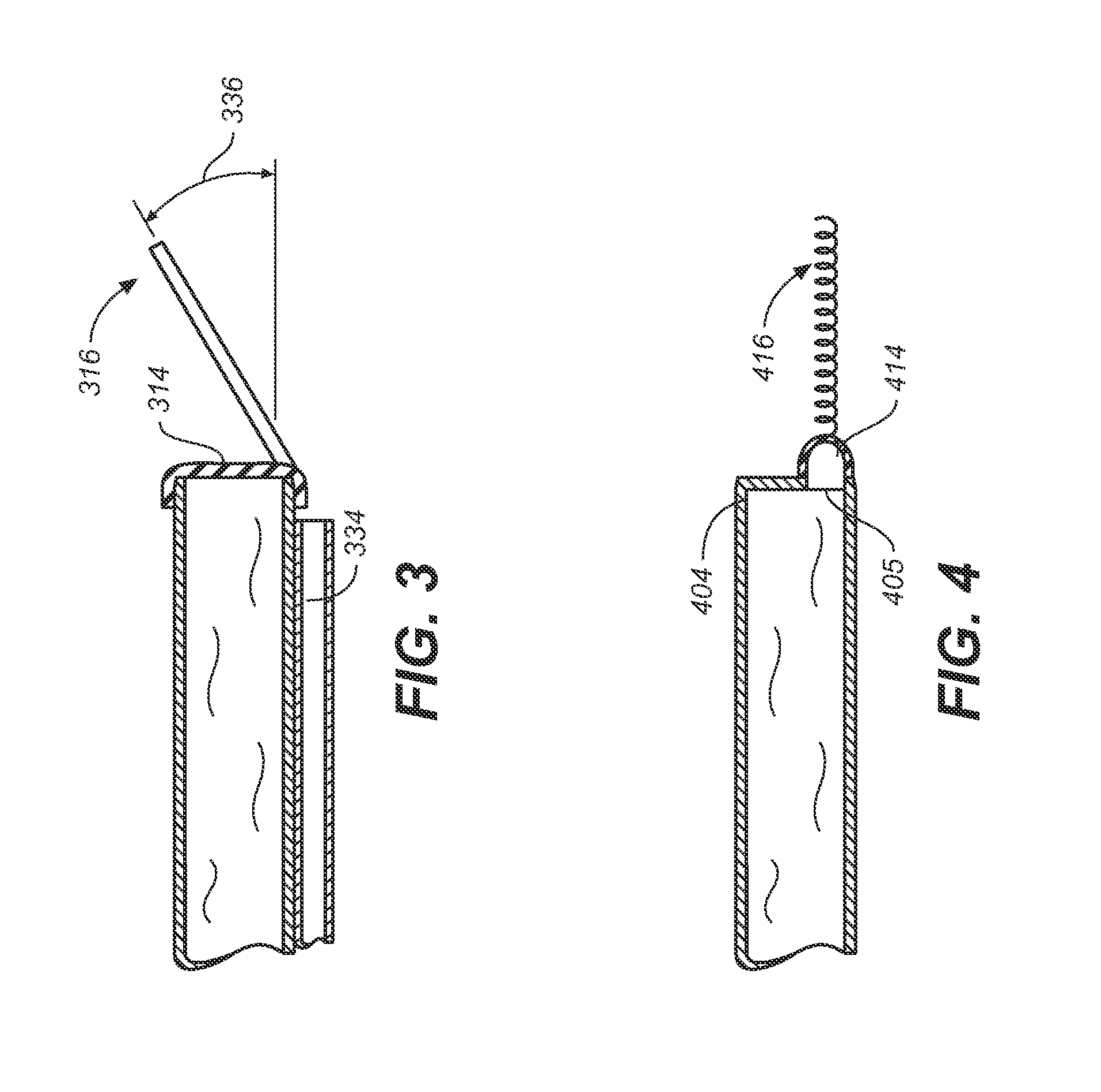
[0020]Specific embodiments of the present invention are now described with reference to the figures, wherein like reference numbers indicate identical or functionally similar elements. The terms “distal” and “proximal” are used in the following description with respect to a position or direction relative to the treating clinician. “Distal” or “distally” are a position distant from or in a direction away from the clinician. “Proximal” and “proximally” are a position near or in a direction toward the clinician. The term “hydrodynamic” is used in the following description with respect to being related to or operated by the force of a liquid in motion.

[0021]The following detailed description is merely exemplary in nature and is not intended to limit the invention or the application and uses of the invention. Although the description of the invention is in the context of treatment of blood vessels such as the cranial, coronary, carotid and renal arteries, the invention may also be used i...


PUM


Abstract

A catheter apparatus for removing an obstruction within a body lumen includes an elongate tubular shaft defining a lumen and a flexible membrane that fluidly seals the distal end of the tubular shaft. At least one cutting element or tool is attached to and distally extends from the flexible membrane. An actuating mechanism is operatively connected to a proximal end of the tubular shaft. The actuating mechanism displaces a fluid disposed within the lumen of the tubular shaft in such a manner that the fluid oscillates the flexible membrane and the cutting element attached thereto. Accordingly, the catheter apparatus uses pulsatile fluid flow through the tubular shaft to transmit energy from the driving mechanical at the proximal end of the catheter apparatus to the flexible membrane at the distal end of the catheter apparatus. The transmitted energy causes the cutting element to oscillate and break up a target blood clot.

Description

FIELD OF THE INVENTION[0001]The invention relates to a hydrodynamic thrombectomy catheter device for percutaneous removal of clots or obstructions within the vascular system.BACKGROUND OF THE INVENTION[0002]Human blood vessels may become occluded or completely blocked by thrombi (blood clots), which reduce the blood carrying capacity of the vessel. Some conditions associated with blood clots include deep vein thrombosis, stroke, and acute myocardial infarction. Blood clots may appear in the brain, veins, lungs, heart, or arteries. If the blockage occurs at a critical place in the circulatory system, serious and permanent injury, or even death, can occur.[0003]To prevent such adverse consequences, some form of medical intervention is usually performed when significant occlusion is detected. Thrombectomy is a term used to refer to a technique that breaks up or removes a blood clot to allow increased blood flow through the vessel. One technique to remove a blood clot includes infusing ...

Claims


Application Information

Patent Timeline
Patent Type & Authority Applications(United States)
IPC IPC(8): A61B17/22
CPCA61B17/22A61B2017/00539A61B2017/2215A61B2017/2212A61B2017/22034
Inventor MAUCH, KEVINARREGUIN, MARIA
Owner MEDTRONIC VASCULAR INC
Why Eureka
Try Eureka