
Natural Gas Liquefaction System with Turbine Expander and Liquefaction Method Thereof

a technology of natural gas liquefaction and turbine expander, which is applied in the direction of liquefaction, lighting and heating apparatus, solidification, etc., can solve the problems of increasing entropy, occupying a large portion of efficiency loss, and reducing so as to increase the efficiency of the whole refrigeration cycle

Inactive Publication Date: 2010-02-04
KOREA ADVANCED INST OF SCI & TECH
View PDF6 Cites 20 Cited by
  • Summary
  • Abstract
  • Description
  • Claims
  • Application Information

AI Technical Summary

Benefits of technology

[0006]Embodiments of the present invention advantageously provide a natural gas liquefaction system with a turbine expander that can improve the efficiency of the whole refrigeration cycle by using the turbine expander, instead of the throttling process that uses the conventional Joule-Thomson throttling valve that is used as a final throttling means in a conventional natural gas liquefaction system, and a liquefaction method thereof.
[0017]According to the natural gas liquefaction system of the present invention using mixed refrigerant with the turbine expander has an effect of increasing the efficiency of the whole refrigeration cycle by using the turbine expander, instead of the throttling process using the conventional Joule-Thomson throttling valve as a final throttling means in the conventional natural gas liquefaction system.

Problems solved by technology

However, the throttling process using the Joule-Thomson valve increases entropy due to embedded irreversibility and this becomes the main cause for decreasing the efficiency of the whole refrigeration cycle.
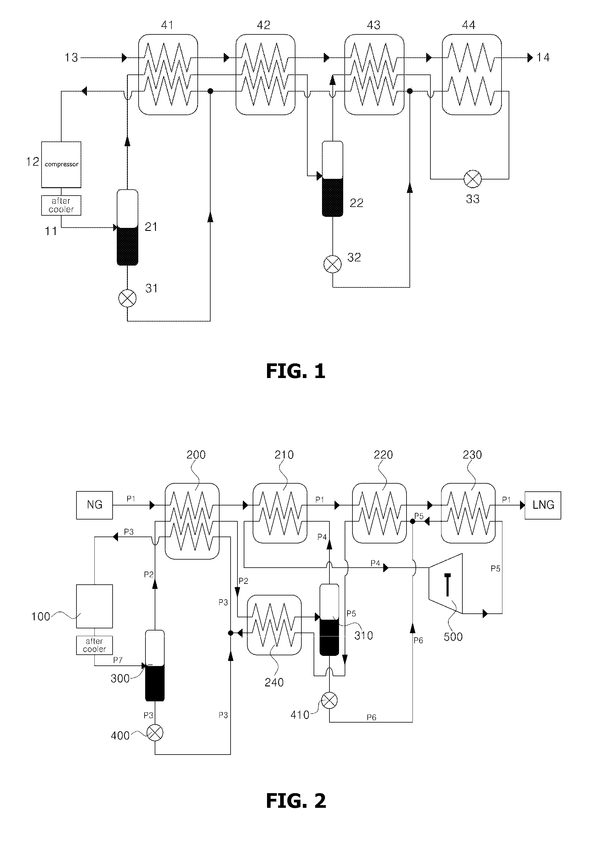
Among several expansion processes, the throttling process of two-phase flow at the throttling valve 33 with lowest temperature occupies a large portion of efficiency loss.

Method used


Image

  • Natural Gas Liquefaction System with Turbine Expander and Liquefaction Method Thereof
  • Natural Gas Liquefaction System with Turbine Expander and Liquefaction Method Thereof

Examples


Embodiment Construction

[0021]Hereinafter, the present invention will be described with reference to the accompanying drawings.

[0022]Prior to this, terms or words used in the specification and claims should not be construed as limited to a lexical meaning, and should be understood as appropriate notions by the inventor based on that he / she is able to define terms to describe his / her invention in the best way to be seen by others. Therefore, embodiments and drawings described herein are simply exemplary and not exhaustive, and it will be understood that various modifications and equivalents may be made to take the place of the embodiments.

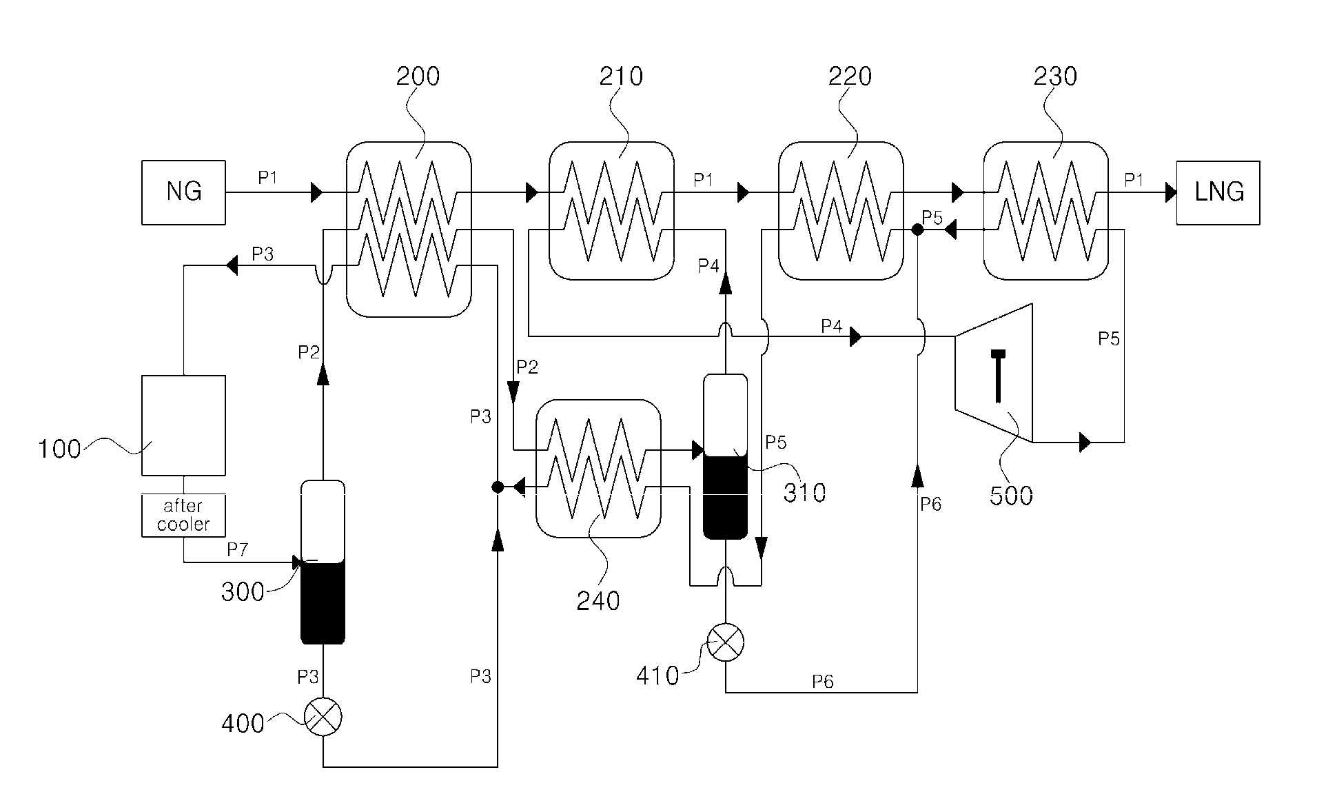
[0023]FIG. 2 is a schematic view showing a natural gas liquefaction cycle with a turbine expander according to one embodiment of the present invention.

[0024]As shown in FIG. 2, the natural gas liquefaction cycle using the turbine expander of the present invention comprises a compressor 100, at least one vapor-liquid separator 300 or 310, a plurality of heat exchangers 200,...


PUM


Abstract

A natural gas liquefaction system with a turbine expander is provided that can improve the efficiency of the whole refrigeration cycle by using the turbine expander, instead of the throttling process that uses the conventional Joule-Thomson throttling valve that is used as a final throttling means in a conventional natural gas liquefaction system, and a liquefaction method thereof. The natural gas liquefaction cycle provided with the turbine expander of the present invention comprises a compressor 100, at least one vapor-liquid separator 300 or 310, a plurality of heat exchangers 200, 210, 220, 230 and 240, at least one Joule-Thomson throttling valves (below to be called JT valve) 400 and 410, a turbine expander 500, and connecting lines composed of plurality of pipes P1, P2, P3, P4, P5, P6 and P7 to connect these components.

Description

CROSS-REFERENCE TO RELATED APPLICATIONS[0001]This application claims priority to foreign Patent Application KR 10 2008 0075165, filed on Jul. 31, 2008, the disclosure of which is incorporated herein by reference in its entirety.FIELD OF THE INVENTION[0002]The present invention relates to a natural gas liquefaction system with a turbine expander, and specifically to a natural gas liquefaction system with a turbine expander that can improve the efficiency of the whole refrigeration cycle by using the turbine expander, instead of the throttling process that uses the conventional Joule-Thomson throttling valve that is used as a final throttling means in a conventional natural gas liquefaction system, and a liquefaction method thereof. In particular, the present invention relates a natural gas liquefaction system with a turbine expander for cooling natural gas by indirect heat exchange with the expanded refrigerant stream supplied from the turbine expander in which a refrigerant in a sup...

Claims


Application Information

Patent Timeline
IPC IPC(8): F25J1/00
CPCF25J1/0022F25J1/005F25J1/0265F25J1/0212F25J1/0055F25J1/02F25J3/00
Inventor JEONG, SANG KWONHWANG, GYU WANBAEK, SEUNG WHAN
Owner KOREA ADVANCED INST OF SCI & TECH
Learn More