[0008]Embodiments disclosed herein provide a surgical instrument that integrates multiple surgical functions, providing the surgical personnel a way to shorten the
operating time and increase the efficiency and accuracy of surgical steps. Some embodiments of the surgical instrument disclosed herein include mechanisms for reduction and distraction. Some embodiments of the surgical instrument disclosed herein include mechanisms for reduction, distraction, and compression. Embodiments of the surgical instrument disclosed herein can allow surgical personnel to distract affected vertebrae, hold them in a distracted state, and perform a reduction to correct a
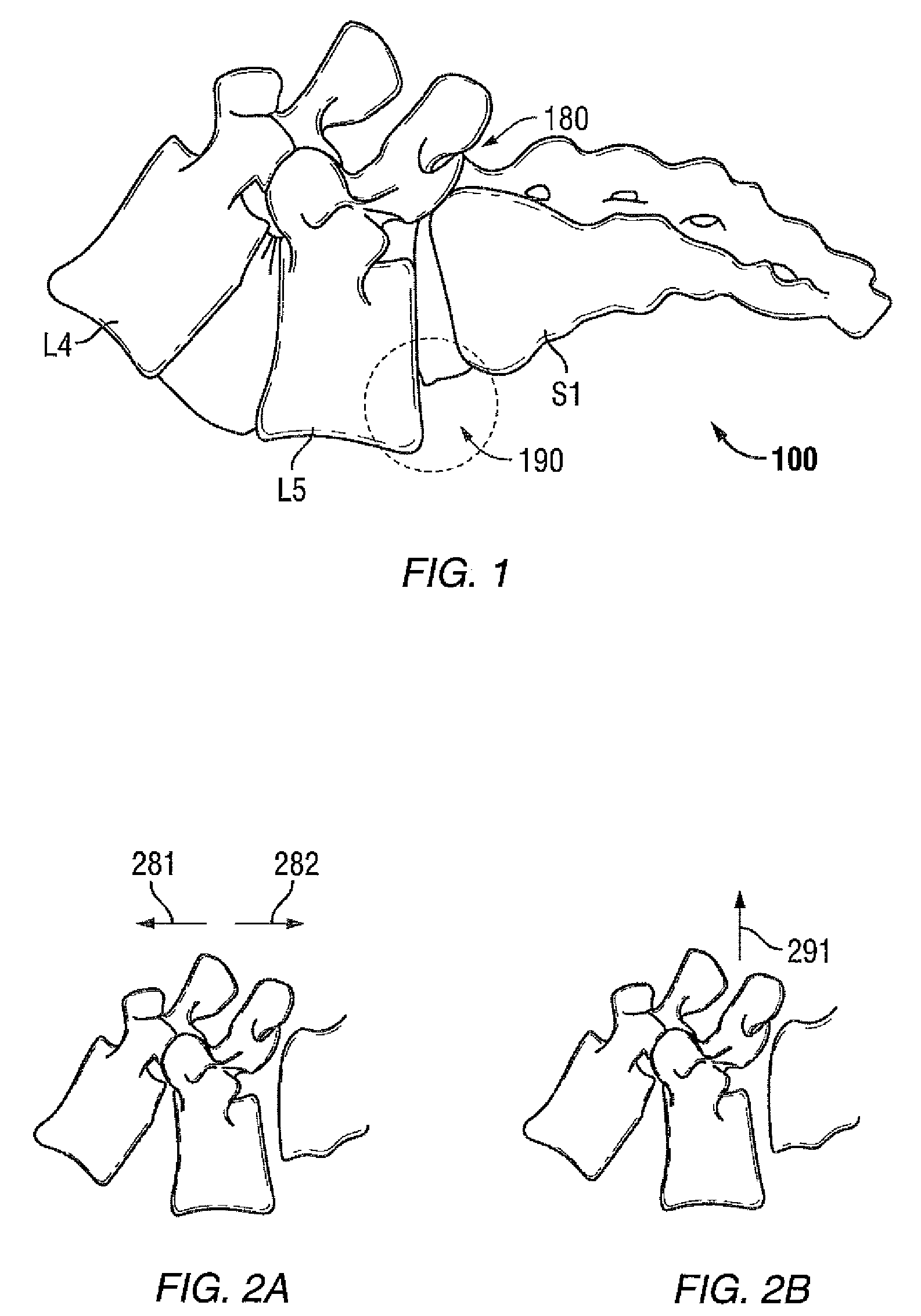
spondylolisthesis without having to switch out one instrument for another. Some embodiments of the surgical instrument disclosed herein can be particularly useful for reducing difficult spondylolisthesis during
posterior fixation.
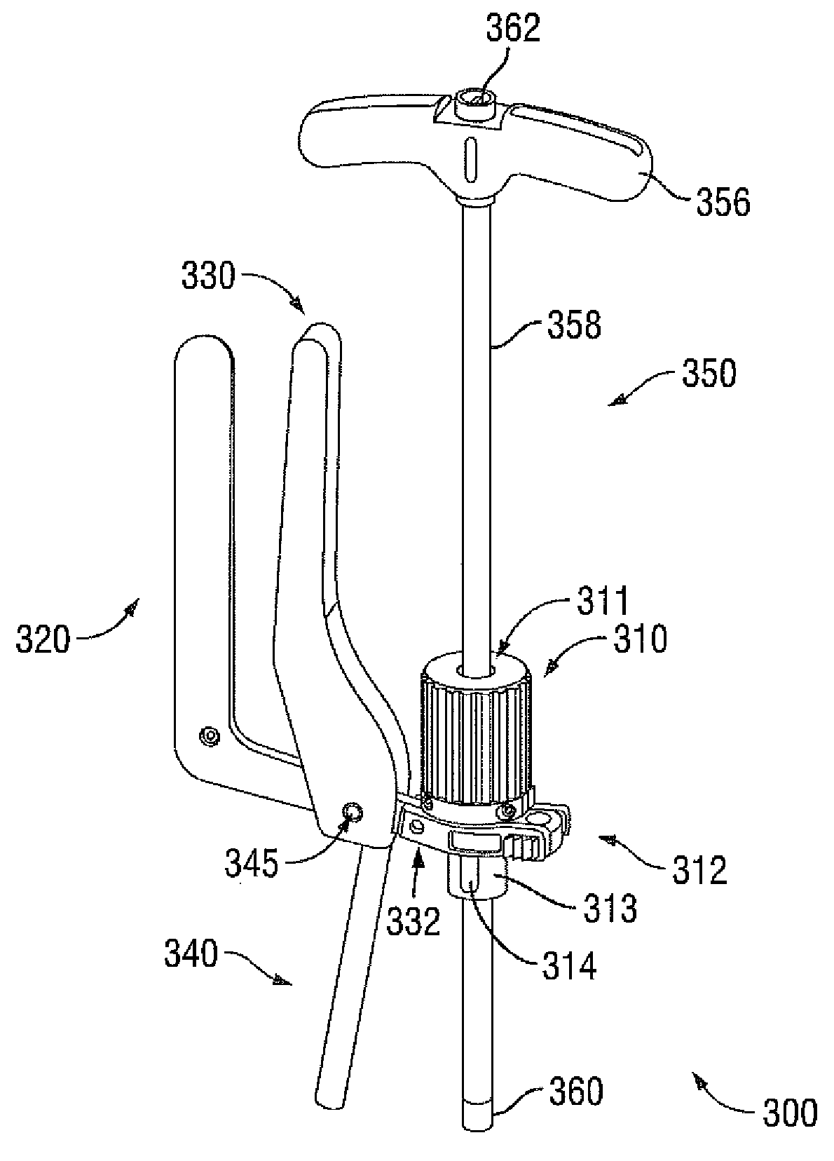
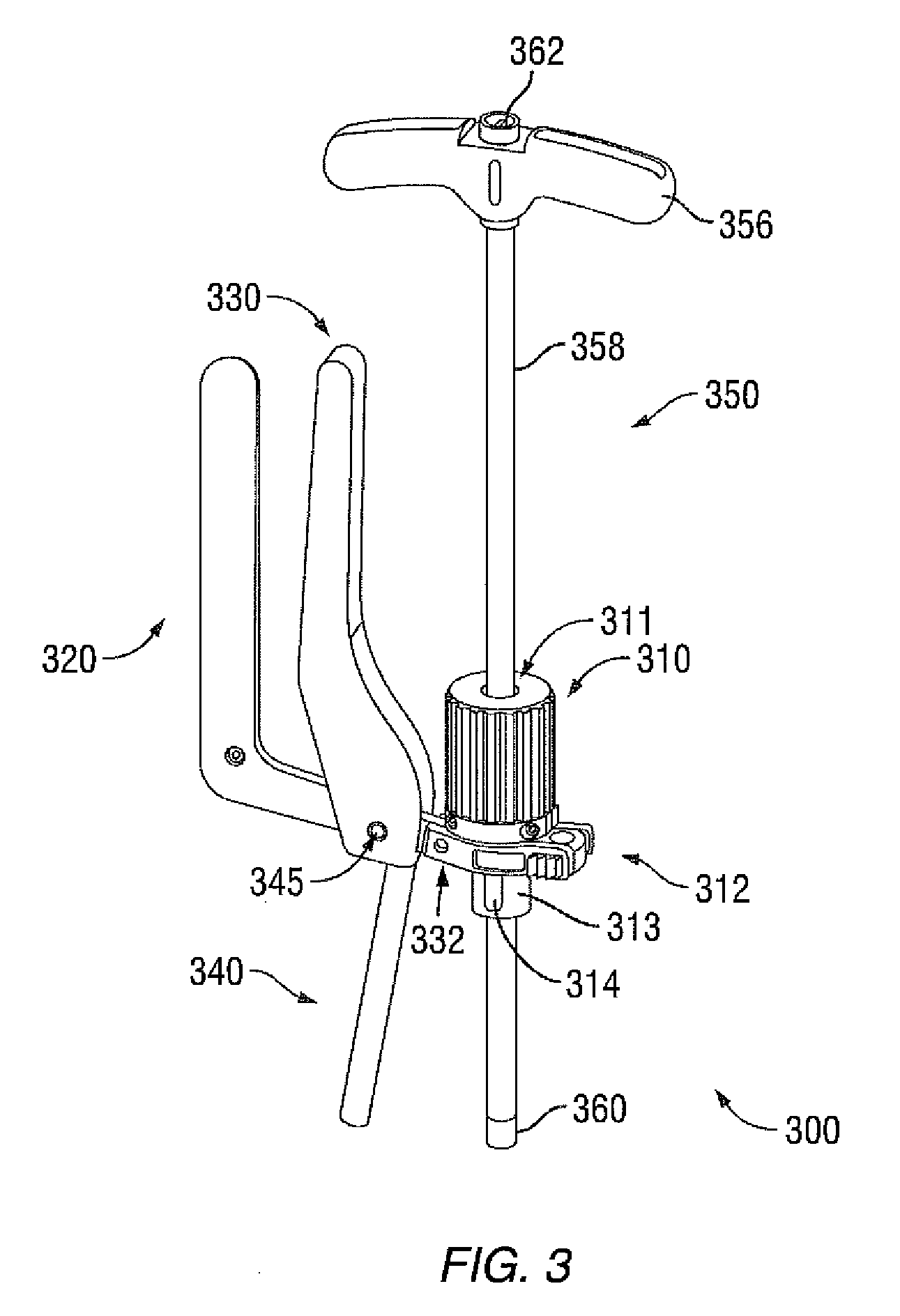
[0009]In some embodiments, a surgical instrument with integrated mechanisms for reduction and distraction may comprise a reducer knob, a reducer tube coupled to the reducer knob, a connecting element coupled to the reducer knob and the reducer tube, a common handle pivotally coupled to the connecting element, and a shaft fixedly attached to or made part of the common handle. The reducer knob, the connecting element, and the reducer tube may have an inner
diameter that accommodates a distractor handle, which, in one embodiment, may be the shaft of a driver such as a closure top driver. For distraction, a surgeon may squeeze the common handle and the distractor handle together, moving them toward one another. This motion increases a distance between the shaft of the common handle and the shaft of the distractor handle under the reducer tube. For reduction, the surgeon may turn the reducer knob to adjust a height of the reducer tube. One end of the reducer knob may have an inner
diameter sufficiently large to accommodate an outer
diameter of the reducer tube such that a portion of the reducer tube may be retracted into the reducer knob.
[0010]In some embodiments, the surgical instrument further includes a compressor handle coupled to the connecting element and the common handle. For compression, the surgeon may squeeze the common handle and the compressor handle together, moving them toward each other. This motion decreases the distance between the shaft of the common handle and the shaft of the distractor handle under the reducer tube. In some embodiments, the compressor handle has an L-shape. In some embodiments, the surgical instrument further comprises a dial coupled to the compressor handle and a pivot locking knob coupled to the common handle. In some embodiments, turning the dial adjusts a distance between the compressor handle and the common handle. In some embodiments, locking the pivot locking knob locks the distance between the compressor handle and the common handle.
[0016]In some embodiments, the common handle may have a second shaft such that moving the common handle towards the first shaft of the driver increases a distance between the shaft of the common handle and the shaft of the driver, which extends through the first and second passages. In some embodiments, a reducer tube may be coupled to the reducer knob and having a third passage through which the shaft of the driver is passable. The reducer knob and the reducer tube can work in concert such that turning the reducer knob in a first direction extends a height of the reducer tube and turning the reducer knob in a second direction retracts a portion of the reducer tube into the reducer knob. In some embodiments, the reducer tube may extend longitudinally over an
extender sleeve which may be utilized in a minimally
invasive procedure. In these embodiments, the reducer tube has an inner diameter that accommodates the
extender sleeve and may have cutouts to
straddle a rod. In some embodiments, the reducer tube does not extend over an
extender sleeve. Instead, the reducer tube may have a diameter for pushing against a counter
torque tube. In these embodiments, the reducer tube may have a non-threaded end for engaging the counter
torque tube.
[0017]Some embodiments of a surgical instrument disclosed herein may have various features to reduce the weight, making it easier to handle. In some embodiments, the compressor handle of the surgical instrument may have one or more weight reducing windows. In some embodiments, the common handle of the surgical instrument may have one or more weight reducing windows. As one skilled in the art can appreciate, weight reducing windows, holes, cavities, recesses, and the like may be implemented at various non-structural portions of the surgical instrument.

