Methods for operating a filtration system

a filtration system and filtration method technology, applied in the direction of electrostatic separation details, setting time indication, electric unknown time interval measurement, etc., can solve the problems of high cost of filter replacement, high cost of pac injection, and difficulty in achieving adequate exit levels of mercury per current regulatory standards, so as to reduce the reduce the effect of sorbent injection rate setting

Inactive Publication Date: 2010-02-04
BHA ALTAIR
View PDF15 Cites 22 Cited by
  • Summary
  • Abstract
  • Description
  • Claims
  • Application Information

AI Technical Summary

Benefits of technology

[0018]i) decreasing the sorbent injection rate setting from a first sorbent injection rate setting to an decreased sorbent injection rate setting;
[0019]j) determining whether the decreased sorbent injection rate setting causes the gaseous pollutant emission level to exceed a predetermined maximum gaseous pollutant emission level;

Problems solved by technology

Extended filter life not only saves the cost of filters, it also saves the cost of filter replacement, which is often difficult, costly and requires the baghouse to be taken out of service for a period of time.
The cost of injecting enough PAC such that adequate exit levels of mercury are achieved per current regulatory standards can be a considerable one.
At present, given the potentially longer period between pulse cleanings, filtration systems generally do not take into account efficiencies that may be realized by manipulating sorbent injection rates, fabric filter cleaning cycles and other operational variables.

Method used


Image

  • Methods for operating a filtration system
  • Methods for operating a filtration system
  • Methods for operating a filtration system

Examples


Embodiment Construction

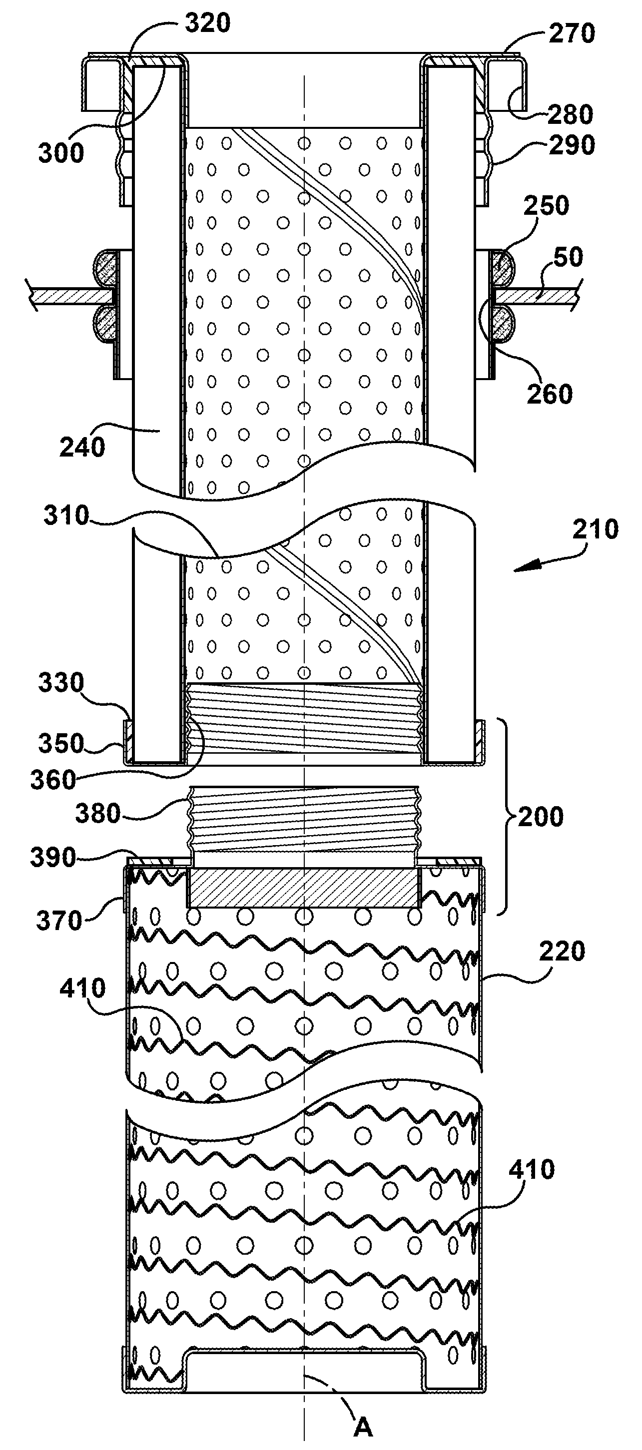
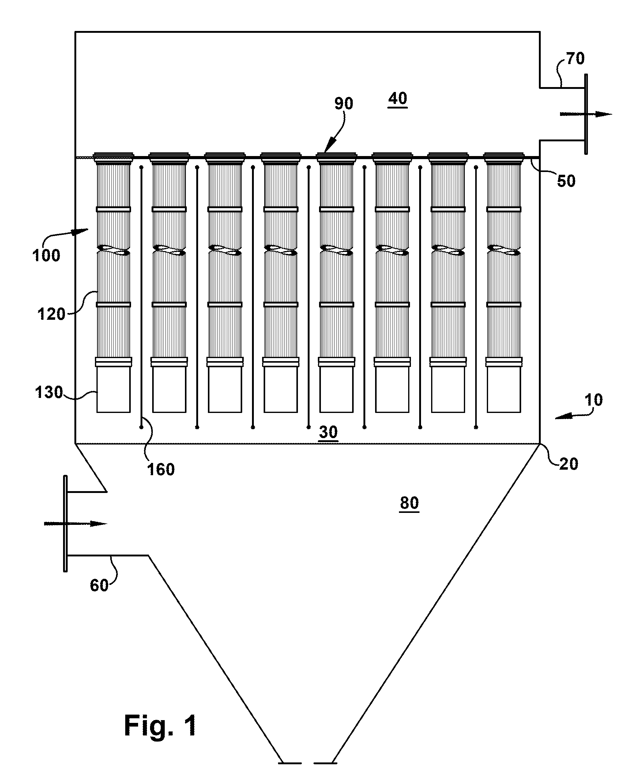
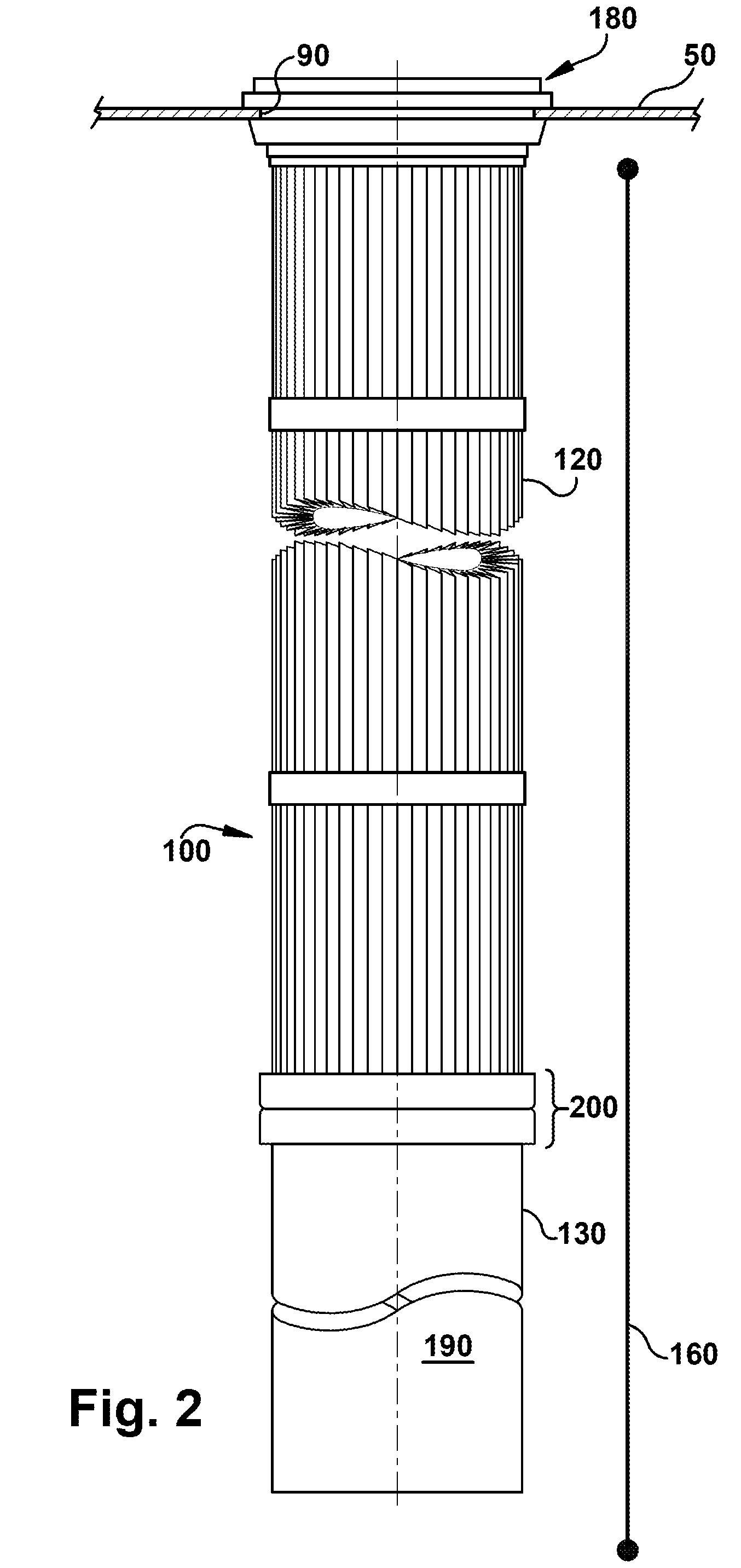
[0032]Referring now to the figures, where the various numbers represent like parts throughout the several views, FIG. 1 is a schematic view, partly in section, of a filtration system in which exemplary embodiments of the present invention may operate. The filtration system 10 generally may include an enclosed housing 20 and a plurality of filter assemblies 100. Each filter assembly 100 may include a filter element 120 and a pre-collector body component 130 extending below and attached to the filter element 120. The system 10 also may include a pre-collector discharge electrode 160. Dirty gas may enter the housing 20 and clean gas may leave. More specifically, the dirty gas may pass adjacent to the pre-collector body components 130 and discharge electrodes 160, which may operate to remove at least a portion of the particulate matter in the dirty gas. Thereafter, the gas may pass through the filter elements 120 where additional particulate matter may be removed. Because of the operati...


PUM

PropertyMeasurementUnit
voltage potentialaaaaaaaaaa
pressure dropaaaaaaaaaa
current densityaaaaaaaaaa

Abstract

A method of operating a filtration system that filters flue gas, which includes particulate matter and a gaseous pollutant. The filtration system may include a fabric filter, which is cleaned with periodic pulse cleanings, a discharge electrode upstream of the fabric filter, which imparts an electric charge to at least some of the particulate matter before the particulate matter collects on the fabric filter, a sorbent, which is injected into the flue gas upstream of the fabric filter and absorbs at least some of the gaseous pollutant, and a fan, which draws the flue gas through the fabric filter. The filtration system may have a pulse cleaning interval setting that may be manipulated by an operator of the filtration system. The pulse cleaning interval setting may be the time between the pulse cleanings. The method may include the steps of: determining a cost of operating the filtration system at a first pulse cleaning interval setting; determining a cost of operating the filtration system at a second pulse cleaning interval setting; and comparing the cost of operating the filtration system at the first pulse cleaning interval setting with the cost of operating the filtration system at the second pulse cleaning interval.

Description

BACKGROUND OF THE INVENTION[0001]The present invention relates generally to filtration systems and methods for removing particulate matter and / or gaseous pollutants from a stream of gas or other fluid. More specifically, but not by way of limitation, the present invention relates to a more cost effective and / or efficient filtration system and method that reduces the use of sorbents and take advantage of other economic benefits.[0002]Fabric filtration is a common technique for separating out particulate matter in a gas stream. In an industrial setting, fabric filtration is often accomplished in a device known as a baghouse. Generally, a baghouse includes a housing that has an inlet for receiving dirty, particulate-laden gas and an outlet through which clean gas leaves the baghouse. The interior of the housing is divided by a tube sheet into a dirty gas or upstream plenum and a clean gas or downstream plenum, with the dirty gas plenum in fluid communication with the inlet and the clea...

Claims


Application Information

Patent Timeline
Patent Type & Authority Applications(United States)
IPC IPC(8): B03C3/017B01D46/30A61F13/15
CPCB01D46/0032B01D46/0068B01D46/04B01D46/50G06Q30/0284B03C2201/04B03C3/155B03C3/41B03C3/49B03C3/74B03C3/06B01D46/71B01D35/06B01D46/48B03C3/017B03C3/34B01D46/02B01D53/02
Inventor TAYLOR, ROBERT W.
Owner BHA ALTAIR
Why Eureka
Try Eureka