Electro-Pneumatic Brake Control Device

Inactive Publication Date: 2010-02-04
WABCO GMBH
View PDF5 Cites 52 Cited by
  • Summary
  • Abstract
  • Description
  • Claims
  • Application Information

AI Technical Summary

Benefits of technology

[0005]Generally speaking, in accordance with the present invention, embodiments of an improved electro-pneumatic brake control

Problems solved by technology

Since venting takes place permanently, the spring store parts of the spring brake cylinders also c

Method used


Image

  • Electro-Pneumatic Brake Control Device
  • Electro-Pneumatic Brake Control Device
  • Electro-Pneumatic Brake Control Device

Examples


Embodiment Construction

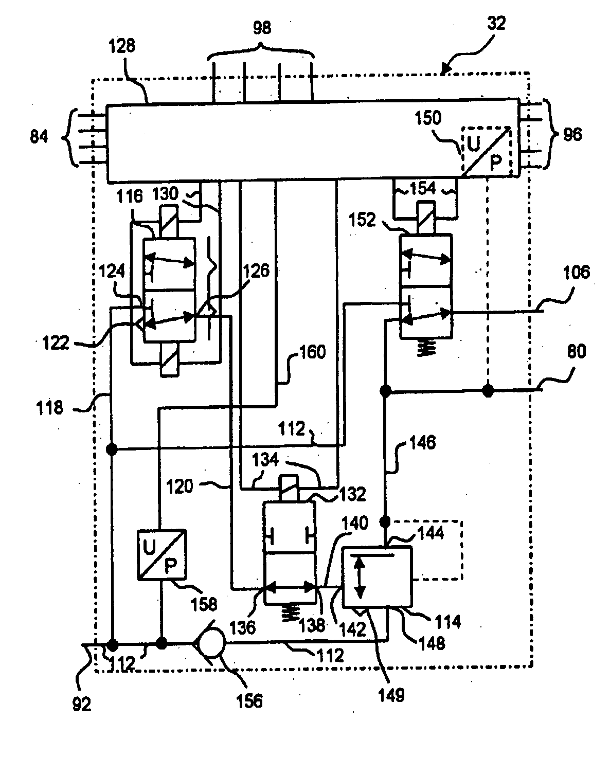
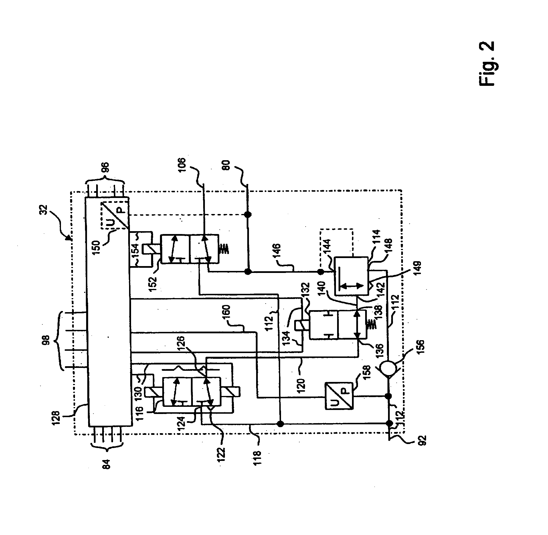
[0013]In accordance with the present invention, the control device for a vehicle parking brake is provided with a compressed air supply line which can be placed in communication with a compressed air reservoir tank for actuating the spring store parts of the spring brake cylinders. An air flow boosting device, such as a relay valve, has an inlet which can be placed in communication with the compressed air supply line and an outlet which can be placed in communication with a compressed air line to the spring store parts of the spring brake cylinders. A pneumatic control input supplies control pressure for controlling the pressure at the outlet of the air flow boosting valve device. An electrically actuated bistable valve is included and has an inlet, which can be placed in communication with the compressed air supply line, and an outlet, which can be placed in communication with the control input of the relay valve. In parked position, the outlet of the bistable valve is in communica...


PUM


Abstract

An electro-pneumatic brake control device is provided for controlling a parking brake of a vehicle having a service brake and a parking brake, the service brake having a brake pedal and pneumatically actuatable brake cylinders operatively connected to the brake pedal for actuating wheel brakes. At least one brake cylinder is a spring brake cylinder with a spring store part for actuating the parking brake. In the event of a failure of the electrical energy supply, the spring store part of the spring brake cylinder is permanently vented by actuating the brake pedal in order to activate the parking brake.

Description

BACKGROUND OF THE INVENTION[0001]The present invention relates generally to an improved electro-pneumatic brake control device for controlling the parking brake of a vehicle.[0002]EP 1 571 061 A1 describes a brake control device and a brake system of the general type under consideration. Such systems provide a service brake, which can be actuated by means of a brake pedal, and a parking brake (often also referred to as a handbrake), which can be actuated by means of an electric signal transducer.[0003]The failure of the electric power supply can be a problematic event in such electrically controlled brake systems as electric components, such as electric control systems and electrically actuated solenoid valves, can no longer be actuated. Furthermore, electric signal transducers for the parking brake can also fail as a result of such power failures. DE 199 53 805 C1 and EP 1 571 061 A1 propose that emergency braking may be initiated automatically whenever the electric power supply fa...

Claims


Application Information

Patent Timeline
IPC IPC(8): B60R21/00B60T13/68
CPCB60T13/683B60T8/327
Inventor BENSCH, UWEFORSTER, HENNINGKIEL, BERND-JOACHIMMENZE, WILFRIEDROSENDAHL, HARTMUTSTRUWE, OTMAR
Owner WABCO GMBH
Why Eureka
Try Eureka