
Cell-adsorbing column

a cell-adsorption column and column technology, applied in the field of new adsorption columns, can solve the problems of high bulk density of nonwoven fabrics, poor control of blood cell removal, and rise of pressure loss during blood circulation, so as to reduce pressure loss, less concern about denaturation and differentiation induction, and reduce the burden on patients

Inactive Publication Date: 2010-02-04
TORAY IND INC
View PDF8 Cites 22 Cited by
  • Summary
  • Abstract
  • Description
  • Claims
  • Application Information

AI Technical Summary

Benefits of technology

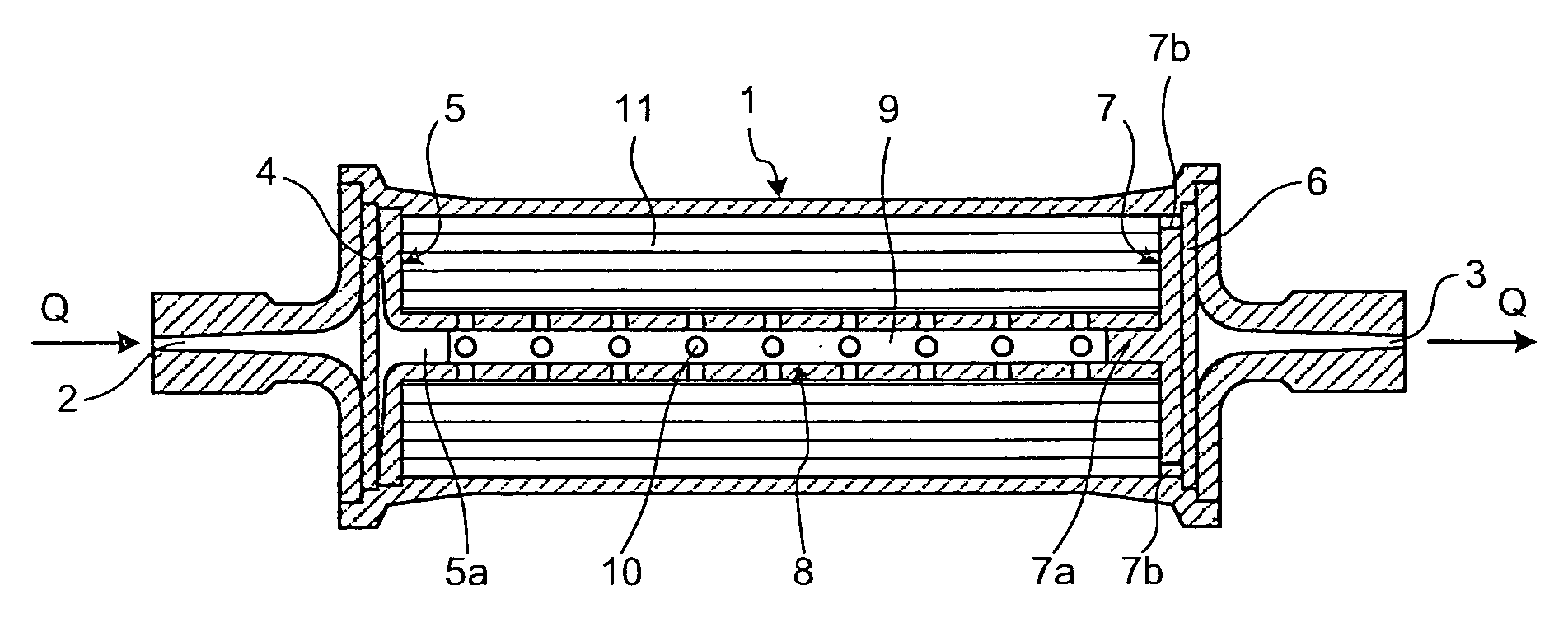
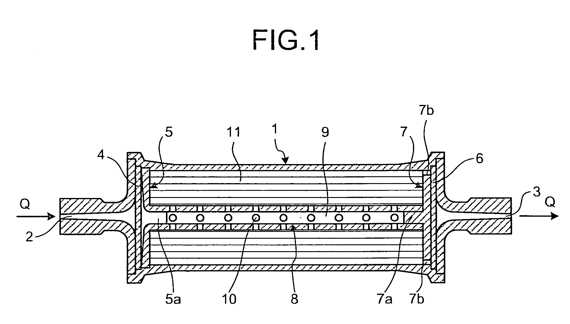
[0016]According to the present invention, it has become possible to provide a cell adsorption column which has the adsorbent with a surface area where there is less concern about denaturation and differentiation induction of cells caused by a contact with the cells, and which has the small scale of an adsorbent-filled volume, and which has the property of compactness for operability and for reducing a burden on patients. It has also become possible to provide a cell adsorption column which can remove not only cells present in blood, particularly activated leukocytes such as granulocytes and monocytes, and cancer cells but also the excessively existing cytokines, and which exhibits a decreased pressure loss.

Problems solved by technology

However, a bulk density of the nonwoven fabric itself is high and the carrier can not control a removal of blood cells well, so still there is concern about a rise of pressure loss during the blood circulation.
As to the adsorbent carrier having a diameter of about 2 mm and composed of acetate cellulose beads, which is disclosed in Patent Document 2, there is no concern about pressure loss, but it is not possible to increase a surface area for adsorption, and thus this is inefficient as the adsorbent carrier.
Alternatively, a reduction of particle diameters leads to a rise of the pressure loss; therefore, this carrier is difficult to be employed.
However, the carrier having a range of 0.05 to 0.10 g / cm3 is poor in shape stability and the carrier having a range of 0.10 to 0.15 g / cm3 is still impractical.

Method used


Image

  • Cell-adsorbing column
  • Cell-adsorbing column

Examples


production example 1

Preparation of Adsorbents 1 to 4

(Nonwovens 1 and 2)

[0106]A sea island composite fiber having 36 islands where the island was further composed of the core / sheath composite was obtained using the following components under the condition of a spinning rate of 850 m / minute and a drawing scale of 3 times.

[0107]Core component of island; polypropylene

[0108]Sheath component of island; 90% by weight of polystyrene and 10% by weight of polypropylene

[0109]Sea component; copolymer polyester (PETIFA) which is ethylene terephthalate as the major repeating unit containing 3% by weight of 5-sodium sulfoisophthalate as a copolymerization component

[0110]Composite ratio (weight ratio); core:sheath:sea=41:41:18

[0111]A nonwoven was obtained by making a sheet-like material composed of 30% by weight of the fiber (diameter: 30 μm) and 70% by weight of polypropylene having a diameter of 22 μm, and giving the needle punch thereto (nonwoven 1). Likewise, a nonwoven was obtained by making a sheet-like material...

production example 2

Preparation of Adsorbents 5 and 6

(Nonwovens 3 and 4)

[0120]A sea island composite fiver having 36 islands where the island was further composed of the core / sheath composite was obtained using the following components under the condition of the spinning rate of 850 m / minute and the drawing scale of 2 times.

[0121]Core component of island; polypropylene

[0122]Sheath component of island; 90% by weight of polystyrene and 10% by weight of polypropylene Sea component; PETIFA

[0123]Composite ratio (weight ratio); core:sheath:sea=41:41:18

[0124]A nonwoven was obtained by making a sheet-like material composed of 30% by weight of the fiber (diameter: 40 μm) and 70% by weight of polypropylene (diameter: 22 μm) and giving the needle punch thereto (nonwoven 3). Likewise, a nonwoven was obtained by making a sheet-like material composed of 68% by weight of the fiber (diameter: 40 μm) and 32% by weight of polypropylene (diameter:22 μm) and giving the needle punch thereto (nonwoven 4).

[0125](Nonwovens 3 ...

production example 3

Preparation of Adsorbents 7 and 8

(Nonwovens 5 and 6)

[0131]A sea island composite fiber having 36 islands where the island was further composed of the core / sheath composite was obtained using the following components under the condition of the spinning rate of 880 m / minute and the drawing scale of 3 times.

[0132]Core component of island; polypropylene

[0133]Sheath component of island; 90% by weight of polystyrene and 10% by weight of polypropylene Sea component; PETIFA

[0134]Composite ratio (weight ratio); core:sheath:sea=41:41:18

[0135]The sea island composite fiber at 30% by weight (diameter: 30 μm) and 70% by weight of polypropylene (diameter: 22 μm) were thoroughly mixed and dispersed using a tuft blender, and passed through a card to make the sheet-like material. Subsequently, a net (thickness: 0.4 mm, diameter of monofilament: 0.3 mm, bulk density: 75 g / m2) having openings of 2 mm square and made from polyester was inserted between the sheet-like materials so that a fiber direction...


PUM

PropertyMeasurementUnit
Timeaaaaaaaaaa
Pressureaaaaaaaaaa
Diameteraaaaaaaaaa

Abstract

In light of such conventional technical problems, it is an object of the present invention to provide a cell adsorption column which has an adsorbent with a surface area where there is less concern about denaturation and differentiation induction of cells caused by a contact of the adsorbent with the cells, and whose adsorbent-filled volume is small, and which has a compact property for improving operability and reducing a burden on a patient. The present invention provides a cell adsorption column filled with an adsorbent containing a fiber whose fiber diameter is 0.5 μm or more and 10 μm or less and having a surface area of 0.5 m2 or more and less than 10 m2, in which the adsorbent-filled volume is 100 mL or less.

Description

TECHNICAL FIELD[0001]The present invention relates to a novel adsorption column, in particular to the adsorption column which is suitable for a blood treatment column used by circulating blood therein. The present invention relates to a cell adsorption column in which an adsorbent in a certain amount is incorporated and which can remove leukocytes in a sufficient amount and is excellent in compact property.BACKGROUND ART[0002]In recent years, various blood treatment columns have been studied, and for example, the columns for the purpose of removing leukocytes and granulocytes (JP Sho 60-193468 A, JP Hei 5-168706 A [Patent Documents 1 and 2]), the columns for the purpose of adsorbing cytokines (JP Hei-10-225515 A, JP Hei 12-237585 A and JP Hei 10-147518 A [Patent Documents 3, 4 and 7]) and the columns for the purpose of simultaneously adsorbing the leukocytes and toxins (JP 2002-113097 A [Patent Document 5]) have been developed. These typically have a filtration material or an adsorb...

Claims


Application Information

Patent Timeline
IPC IPC(8): B01D15/08A61K35/14A61M1/02A61M1/36A61P1/04A61P19/02A61P29/00B01D15/00B01J20/26
CPCA61M1/3633A61M1/3679B01J20/3248B01J20/28023B01J20/28057B01D15/00A61P1/04A61P19/02A61P29/00B01J20/28004B01D15/08A61M2202/0439A61M2230/207
Inventor SHIMAKI, MASAAKI
Owner TORAY IND INC
Learn More