Ultraviolet absorbent composition

a technology of absorbent composition and ultraviolet light, applied in the field of ultraviolet light absorbent composition, can solve the problems of bleedout, inability to solve the above problems, increase in addition amount, etc., and achieve the effect of narrowing the absorbent width, sharper spectral shape, and broadening the spectral shap

Inactive Publication Date: 2010-02-04
FUJIFILM CORP
View PDF5 Cites 16 Cited by
  • Summary
  • Abstract
  • Description
  • Claims
  • Application Information

AI Technical Summary

Benefits of technology

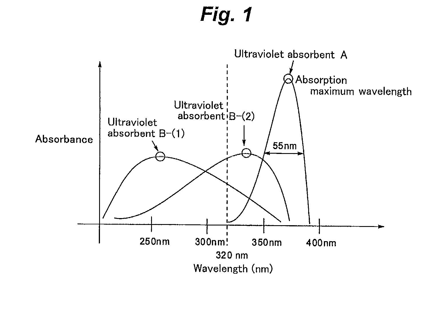
[0009]Further, the inventors studied such ultraviolet-absorbing compounds having such a spectral shape. As described in Sumio Tokita “Chemistry Seminar 9. Color Chemistry” (Maruzen, 1982), p. 150 to 161, the spectral shape of a compound is constantly related to the energy level of its electron states as well as the levels of vibration and rotation. Restriction of the factors of molecular vibration and rotation would be effective in narrowing the absorbent width and giving a sharper spectral shape. However, even when the factors of vibration and rotation are restricted, the spectral shape may broaden, if the structure has side absorption in addition to its main absorption, the intensity of the side absorption is large, and the side absorption occurs in a wavelength range significantly separated from that of the main absorption. It was difficult to sharpen the spectral shape of a common ultraviolet absorbent, such as the benzotriazole- and triazine-based absorbents, which have been generally used as ultraviolet absorbents having broad absorption, for the above reasons. The inventors considered it essential for sharpening the spectral shape to depart from these structures and select a compound in the structure wherein the contribution of vibration and rotation is smaller and there is smaller side absorption. As a result, it was found to be possible to solve the problems in absorption effectively by using the compound represented by any one of formulae (2) to (4), (B-I) and (B-Ia) satisfying the requirements above as the ultraviolet absorbent. The inventors have also found that when the compound represented by any one of formulae (2) to (4), (B-I) and (B-Ia) is used as the ultraviolet absorbent, it is possible to solve the aforementioned problems of compatibility with a polymer and solubility in a solvent.

Problems solved by technology

As a result, the inventors found that it is not easy to solve the above problems with a single molecular compound that does not have a plurality of ultraviolet-absorbing structures.
The increase in addition amount, which may lead to bleed-out, is undesirable.
Thus, when a wavelength range to be blocked reliably and a wavelength range to be transmitted reliably are close to each other, it is quite difficult to satisfy both requirements at the same time.
However, when ultraviolet absorbents properly selected according to the aforementioned finding were used in combination, poor compatibility with the polymer resulted in a problem of bleed-out of the ultraviolet absorbents, and moreover poor solubility in the solvent caused a problem of inferior operating efficiency.
It was difficult to sharpen the spectral shape of a common ultraviolet absorbent, such as the benzotriazole- and triazine-based absorbents, which have been generally used as ultraviolet absorbents having broad absorption, for the above reasons.

Method used


Image

  • Ultraviolet absorbent composition
  • Ultraviolet absorbent composition
  • Ultraviolet absorbent composition

Examples


example 1

Preparation of Ultraviolet Absorbent Composition

[0357]Ultraviolet absorbent composition samples 1 to 45 in combination of ultraviolet absorbents A and B were prepared, as shown in the following Tables 4 and 5. In the following Tables 4 and 5, the ratio of the ultraviolet absorbents A to B(A:B) is expressed by molar ratio.

TABLE 4Formula ofClassificationUltravioletUltravioletUltravioletof UltravioletSampleabsorbent Aabsorbent BA:Babsorbent Babsorbent BRemarks1S-06II-21:1(IIa), (IIb)B-(1)This invention2S-06II-31:1(IIa), (IIb)B-(1)This invention3S-06II-41:1(IIa), (IIb)B-(1)This invention482II-41:4(IIa), (IIb)B-(1)This invention5S-01II-51:1(IIa), (IIb)B-(1)This invention6S-01II-61:1(IIa), (IIb)B-(1)This invention7S-01II-81:1(IIa), (IIb)B-(1)This invention8S-01 II-101:1(IIa), (IIb)B-(1)This invention9S-01II-11:1(IIa), (IIb)B-(1)This invention10S-03II-11:1(IIa), (IIb)B-(1)This invention11S-06II-11:1(IIa), (IIb)B-(1)This invention12S-09II-11:1(IIa), (IIb)B-(1)This invention13S-10II-11:1(IIa...

example 2

Preparation of Molded Plates 101 to 109

[0365]One (1) kg of a polymethyl methacrylate resin (PMMA) and 0.1 g of the composition sample 1 were agitated in a stainless steel tumbler for 1 hour. The mixture was melted and blended by a vent extruder at 230° C. and extruded into pellets for molding by an ordinary method. The pellets were dried at 80° C. for 3 hours, and then, molded into a molded plate 101 having a thickness of 3 mm by an injection molding machine.

[0366]Molded plates 102 to 105 were prepared in a similar manner to the molded plate 101, except that the composition sample 1 was replaced with the composition sample 4, 7, 16, or 18 in preparation of the molded plate 101.

[0367]Alternatively, molded plates 106 to 109 were prepared in a similar manner to the molded plate 101, except that the composition sample 1 was replaced with the composition sample 36, 39, 44 or 45 in preparation of the molded plate 101.

(Evaluation)

[0368]Each molded plate prepared was photoirradiated by a xe...

example 3

Preparation of PET Films 201 to 207

[0371]A transparent coating consisting of 100 g of DIANAL LR-1065 (trade name, manufactured by Mitsubishi Rayon, 40% methylethylketone (MEK) solution of an acrylic resin) and 0.5 g of the composition sample 5 was applied on a 100-μm polyethylene terephthalate (PET) film to be a dry film thickness of approximately 30 μm with a bar coater, and dried to give a PET film 201 having an ultraviolet-absorbing layer.

[0372]PET films 202 to 205 were prepared in a similar manner to the PET film 201, except that the composition sample 5 was replaced with the composition sample 15, 21, 27 or 30 in preparation of the PET film 201.

[0373]Alternatively, PET films 206 and 207 were prepared in a similar manner to the PET film 201, except that the composition sample 5 was replaced with the composition sample 36 or 39 in preparation of the PET film 201.

(Evaluation)

[0374]A solid image in magenta color was printed on an inkjet-recording paper and dried sufficiently by usi...


PUM

PropertyMeasurementUnit
absorption maximum wavelengthaaaaaaaaaa

Abstract

An ultraviolet absorbent composition, containing:
    • at least one kind of ultraviolet absorbent A having an absorption maximum wavelength of from 350 nm to 400 nm, a half value width of 55 nm or less and a molar extinction coefficient of 20,000 or more at the absorption maximum wavelength; and
    • at least one kind of ultraviolet absorbent B having an absorption maximum wavelength of 350 nm or less and showing 30% or more of absorbance at 320 nm of the absorbance at the absorption maximum wavelength.

Description

TECHNICAL FIELD[0001]The present invention relates to an ultraviolet absorbent composition.BACKGROUND ART[0002]Ultraviolet absorbents have been used in combination with various resins for providing the resins with ultraviolet-absorptivity. Both inorganic and organic ultraviolet absorbents are used. The inorganic ultraviolet absorbents (see, for example, JP-A-5-339033 (“JP-A” means unexamined published Japanese patent application), JP-A-5-345639 and JP-A-6-56466) are superior in durability properties such as weather resistance and heat resistance. However, the freedom in selecting the compound is limited, because the absorption wavelength is determined by the band gap of the compound. In addition, there is no inorganic absorbent that absorbs the light in a long-wavelength ultraviolet (UV-A) range of 320 to 400 nm. And any such absorbent that absorbs long-wavelength ultraviolet would have color because it would have absorption also in the visible range. It is known that a film having ...

Claims


Application Information

Patent Timeline
Patent Type & Authority Applications(United States)
IPC IPC(8): F21V9/06
CPCC08K5/005C08L21/00C08K2201/014
Inventor HANAKI, NAOYUKIYAWATA, TOSHIHIKOMIKOSHIBA, HISASHI
Owner FUJIFILM CORP
Why Eureka
Try Eureka