DC power system

Inactive Publication Date: 2010-02-04
VALIDUS DC SYSTEMS
View PDF6 Cites 5 Cited by
  • Summary
  • Abstract
  • Description
  • Claims
  • Application Information

AI Technical Summary

Problems solved by technology

If cooling were to fail for even a small period of time the computer equipment could be severely affected.
With an increase in the power required to operate data center equipment, and its associated heat, the necessity of providing uninterruptible power to the pumps and fans motors during a power outage has become a primary concern.
This process, from utility power outage until the load is transferred to generators, can take up to 60 seconds and in some cases longer, thereby leaving the critical cooling systems off line for a

Method used


Image

  • DC power system
  • DC power system

Examples


Embodiment Construction

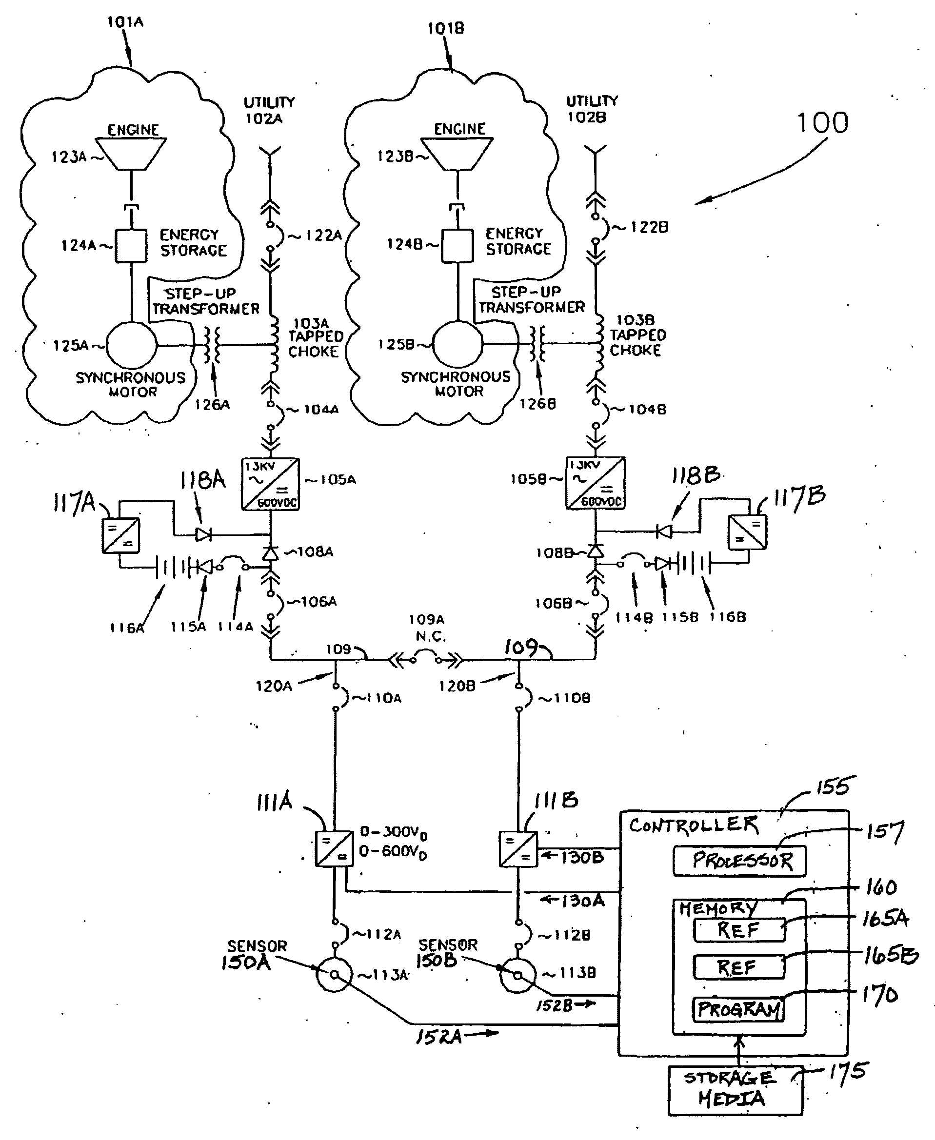
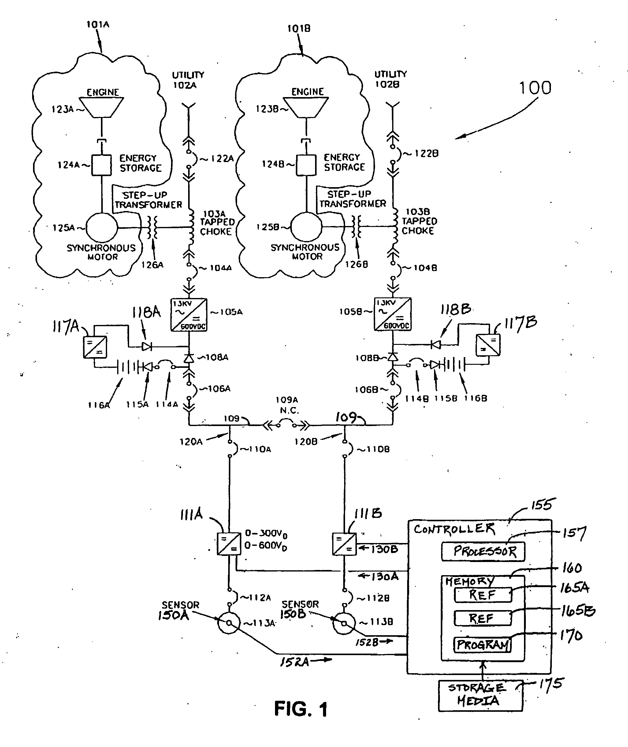
[0008]FIG. 1 is a schematic of a redundant DC power system, i.e., system 100. System 100 is configured as a 2N power system, where N is the amount of power required to properly support power loads. System 100 includes generators 101A, B, rectifiers 105A, B, motor drives 111A, B, motors 113A, B, sensors 150A, B, and a controller 155.

[0009]In brief, system 100 provides DC power to motor drives 111A, B, that in turn drive motors 113A, B. Via sensors 150A, B, controller 155 monitors parameters associated with the operation of motors 113A, B, and in turn controls motor drives 111A, B so that the sensed parameters are maintained within a desired range.

[0010]System 100 receives alternating current (AC) from utilities 102A, B. The AC current from utility 102A is coupled through a breaker 122A, and the AC current from utility 102B is coupled through a breaker 122B. Breakers 122A, B protect circuits downstream of breakers 122A, B, and can be implemented as either circuit breakers or fuses.

[00...


PUM


Abstract

There is provided a system that includes a power feed that distributes a direct current (DC) voltage in a building. The DC voltage is In a range of about 300-600 volts DC. The system also includes a motor, and a motor drive. The motor drive receives the DC voltage via the power feed, and from the DC voltage, derives an output that drives the motor.

Description

BACKGROUND OF THE INVENTION[0001]1. Field of the Invention[0002]The present invention relates to a highly reliable, redundant direct current (DC) power system that provides modulated power to motors that are utilized in the cooling of data centers and critical infrastructures.[0003]2. Description of the Related Art[0004]Critical infrastructures like data centers, telecommunications center and others that require high density critical uptime power for processing storage and communications have been steadily growing with regard to their power and cooling requirements. In these critical infrastructure applications, it is imperative to not only supply highly reliable power, but also equally reliable cooling. If cooling were to fail for even a small period of time the computer equipment could be severely affected. Additionally, due to the extreme energy use of these centers, it is imperative to design and apply systems that are not only resilient but also highly efficient.[0005]Tradition...

Claims


Application Information

Patent Timeline
IPC IPC(8): H02J1/10
CPCH02J9/061H02J1/10H02K47/12H02J9/00
Inventor KRAUS, RUDYGROSS, PETER
Owner VALIDUS DC SYSTEMS
Why Eureka
Try Eureka