Method and apparatus for identifying orientation of a stationary rotor in a sensor-less pmsm

a stationary rotor and orientation technology, applied in the direction of motor/generator/converter stopper, starter details, dynamo-electric converter control, etc., can solve the problems of sudden acceleration of the rotor (possibly in the wrong direction), difficult to determine the position of the rotor, and undesirable abrupt and unpredictable motion

Active Publication Date: 2010-02-04
ROCKWELL AUTOMATION TECH
View PDF4 Cites 27 Cited by
  • Summary
  • Abstract
  • Description
  • Claims
  • Application Information

AI Technical Summary

Benefits of technology

[0016]It is thus an object of at least one embodiment of the invention to provide extremely rapid assessment of rotor position with minimal rotor motion.
[0023]It is thus an object of at least one embodiment of the invention to provide a simple yet high-resolution method of determining rotor axis independent of the number of stator poles.

Problems solved by technology

Unfortunately, when the rotor is moving at a low speed or stationary, the back-EMF is low or nonexistent making it difficult to determine rotor position.
Starting a PMSM motor without knowing the rotor position causes sudden accelerations of the rotor (possibly in the wrong direction) as the rotor attempts to align itself with the generated field.
In many important motor control applications, such abrupt and unpredictable motion is undesirable.
One limitation to this approach is that special hardware may be required.

Method used


Image

  • Method and apparatus for identifying orientation of a stationary rotor in a sensor-less pmsm
  • Method and apparatus for identifying orientation of a stationary rotor in a sensor-less pmsm
  • Method and apparatus for identifying orientation of a stationary rotor in a sensor-less pmsm

Examples


Embodiment Construction

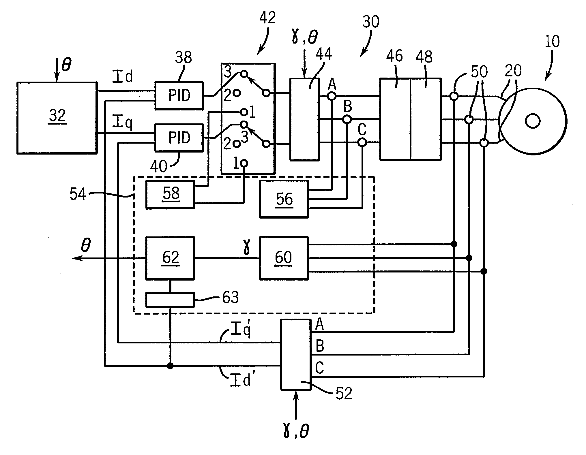
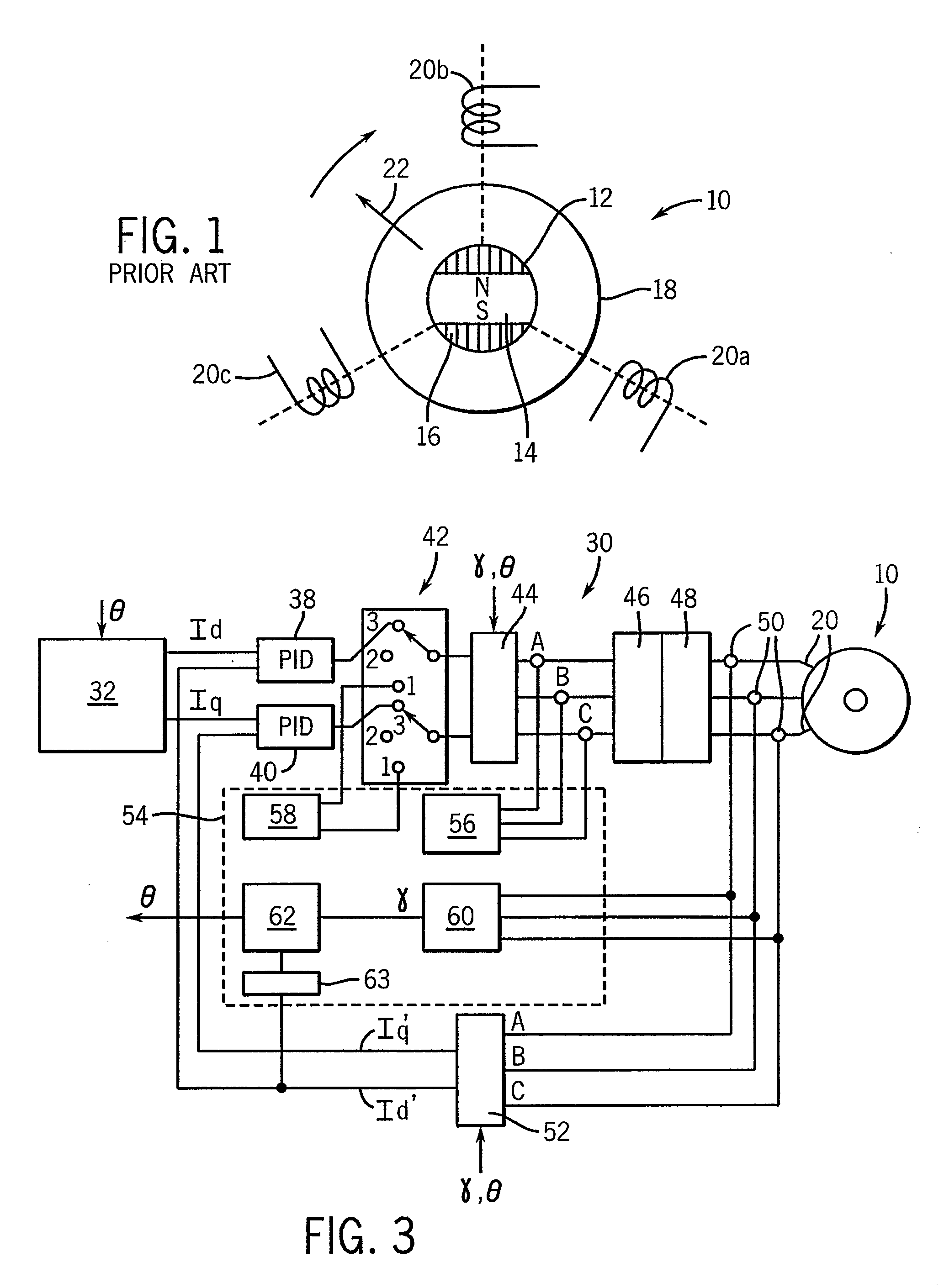
[0034]Referring now to FIG. 1, a PMSM motor 10 provides a rotor 12 attached to a rotatable shaft (not shown) for rotation about an axis through the center of the rotor 12 perpendicular to the plane of the figure. The rotor 12 includes a permanent magnet 14 and ferromagnetic flux directors 16. For clarity, a rotor having a single pole pair (e.g. only a single north and south pole) is shown; however, it will be understood that the present invention is equally applicable to multi-pole rotors.

[0035]The rotor 12 may be surrounded by a stator 18 having one or more coils 20a, 20b, and 20c shown here positioned at regular angles of 120° about the rotor 12. Again additional coils may be provided according to techniques well known in the art for motors having larger numbers of poles.

[0036]Generally, appropriately phased signals may be applied to each of coils 20a, 20b and 20c to produce a rotating magnetic field vector 22 synchronously attracting the rotor 12 to drive the motor 10.

[0037]Refer...


PUM


Abstract

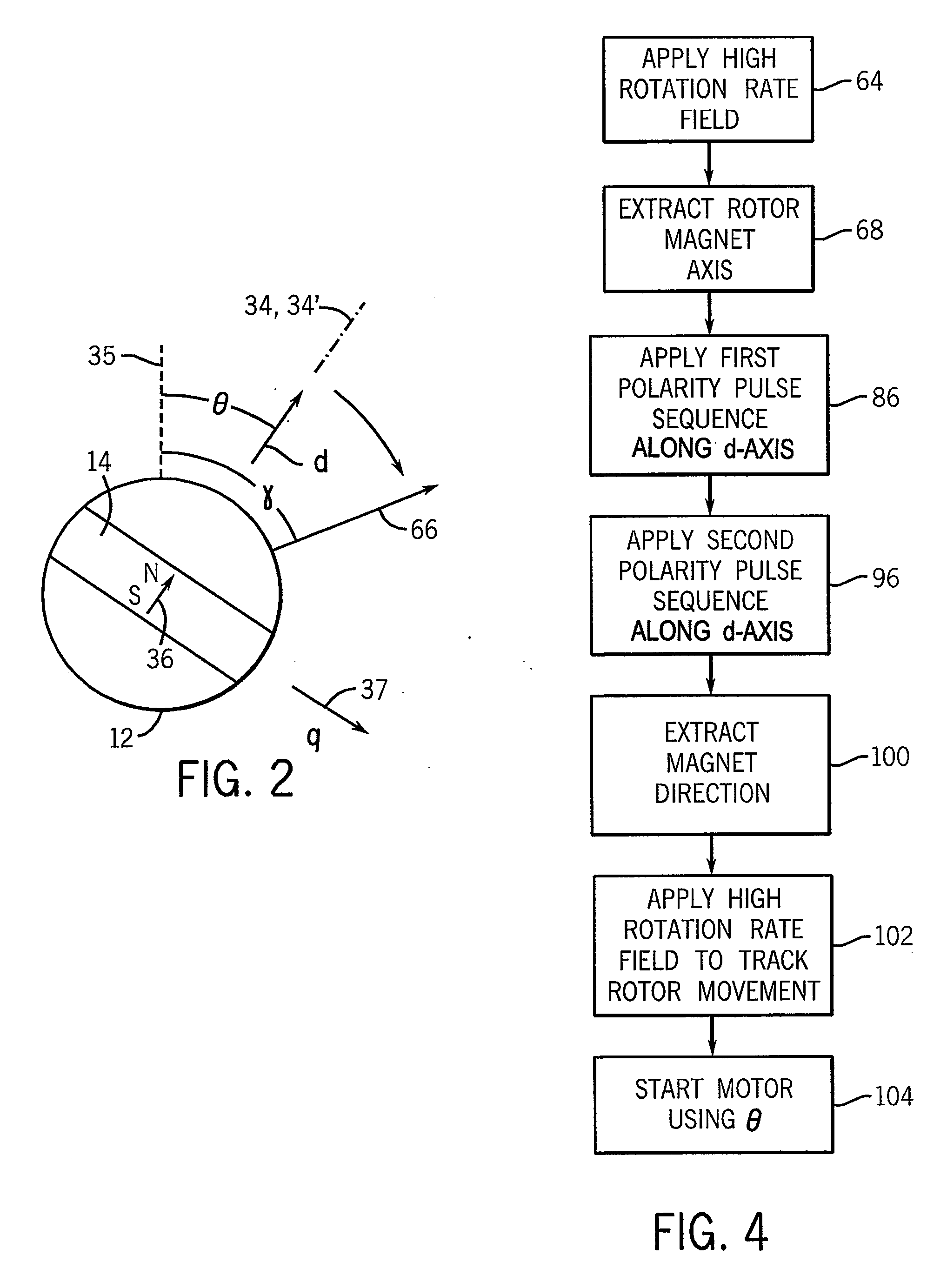
A method and apparatus for determining rotor position in a stationary rotor of a sensor-less permanent magnet synchronous machine that employs a rotating magnetic field to identify a magnetic axis of the stator without a magnetic direction and then determines magnetic direction by applying pulses along the magnet axis in two polarities.

Description

CROSS-REFERENCE TO RELATED APPLICATIONS[0001]—STATEMENT REGARDING FEDERALLY SPONSORED RESEARCH OR DEVELOPMENT[0002]—BACKGROUND OF THE INVENTION[0003]The present invention relates to electric motors and in particular to permanent magnet synchronous machines (PMSM) and more particularly to a method and apparatus for determining the starting position of the rotor of a PMSM without a position sensor such as a resolver.[0004]Permanent magnet synchronous machines are electric motors having a rotor holding a permanent magnet that may turn about an axis within a stator. The stator holds conductive coils that may be energized to create a rotating magnetic field. The rotating magnetic field is coordinated with the rotor position to draw the rotor along synchronously.[0005]Simple PMSM's employ power transistors to switch the electrical currents in the stator coils to create the necessary rotating magnetic field. “Sensor-less” PMSM's eliminate the rotor position sensors and deduce rotor positio...

Claims


Application Information

Patent Timeline
Patent Type & Authority Applications(United States)
IPC IPC(8): H02P6/20
CPCH02P6/185H02P21/146H02P21/0053H02P21/32H02P21/18
Inventor LIU, JINGBONONDAHL, THOMASSCHMIDT, PETERROYAK, SEMYONHARBAUGH, MARK
Owner ROCKWELL AUTOMATION TECH
Why Eureka
Try Eureka