
Communication System Fault Location Using Signal Ingress Detection

a technology of communication system and fault location, applied in the field of communication system condition monitoring and maintenance, can solve problems such as increased noise, difficult detection of egress signals, and damage to lasers

Inactive Publication Date: 2010-02-04
COMSONICS
View PDF3 Cites 37 Cited by
  • Summary
  • Abstract
  • Description
  • Claims
  • Application Information

AI Technical Summary

Benefits of technology

[0009]It is therefore an object of the present invention to provide a system and method of providing closed-loop detection and location of shielding flaws in a cable communication system through production of signal ingress in a controlled manner which does not cause malfunction of the cable communication system.
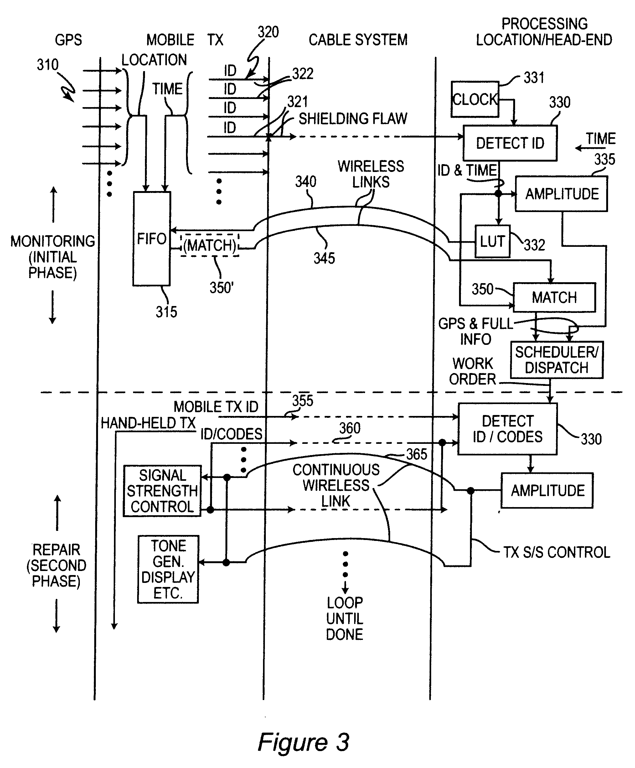
[0012]In accordance with a further aspect of the invention, an apparatus for locating a shielding flaw in a cable communication system is provided, including an arrangement for transmitting a signal for ingress into a cable communication system, an arrangement for controlling signal strength of said signal responsive to a received signal indicating signal strength of an ingress signal in the cable communication system, and an arrangement for generating a signal perceptible to a user indicating signal strength of the ingress signal in the cable communication system and compensated for changes in signal strength due to changes in transmitted signal strength.

Problems solved by technology

Signal egress is currently becoming much less of a problem in regard to interfering with other communications due to the reduction of the extent of use of coaxial cables in cable distribution networks whereas upstream signaling involves use of amplifiers and modulated lasers to couple signals originating the coaxial cable portions of the network into fiber-optic portions of the network and ingress of signals at excessive levels can overload such lasers by driving them into non-linear regions of operation (e.g. saturation) which greatly increases noise while often blocking or at least effectively attenuating the transmission of information-bearing signals (e.g. greatly decreasing the signal to noise ratio (SNR) beyond where information can be reliably communicated) and possibly causing damage to the lasers.
Additionally, increasing use of digital transmission has made egress signals much more difficult to detect since the signals tend to more closely resemble noise and only the carrier signal frequency can be used for reliable detection of signal egress.
Therefore, ingress of signals into a cable communication system is becoming of increased concern while the importance of signal egress is diminishing.
Nevertheless, signal egress and ingress are symmetrical effects due to the same types of flaws in shielding of the coaxial cables employed in cable communication systems which must be monitored and repaired to maintain communication system efficiency and proper performance.
While detection of signal egress has been effective in the past for detection of such flaws, changes in the signals communicated have made it considerably less so and circumstances which may make flaw detection by signal egress detection impractical if not impossible are certainly foreseeable.
Conversely, while signal ingress is becoming of much greater importance, the ability to detect shielding flaws through which signal ingress can occur are diminishing while the intentional production of signal ingress has been impractical for a number of reasons (particularly for system maintenance purposes since it does not, itself, provide closed-loop feedback for location of flaws which is available when detecting signal egress) and certainly contraindicated in view of the malfunctions that may be caused in cable communication systems of current designs capable of providing upstream signaling.

Method used


Image

  • Communication System Fault Location Using Signal Ingress Detection
  • Communication System Fault Location Using Signal Ingress Detection
  • Communication System Fault Location Using Signal Ingress Detection

Examples


Embodiment Construction

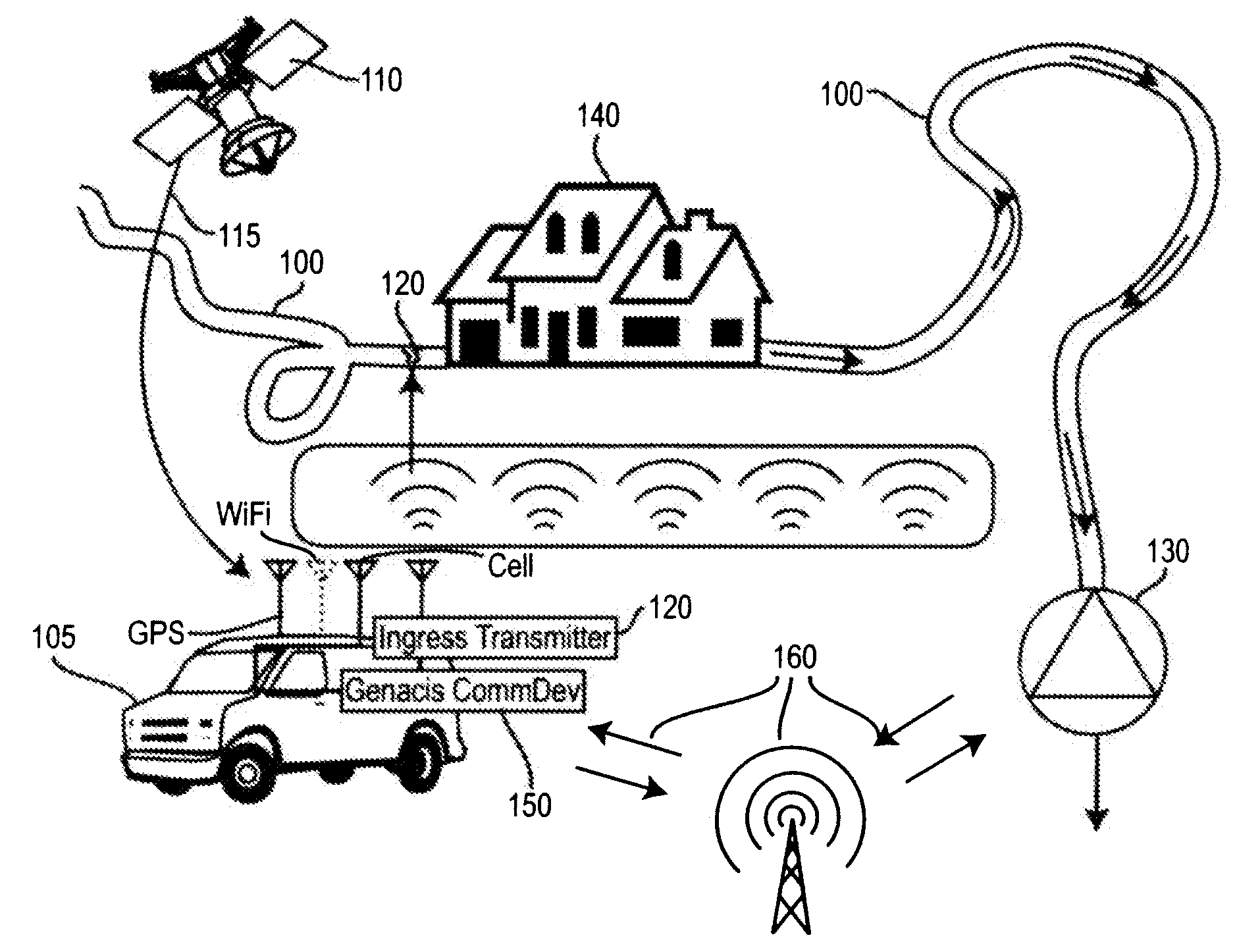
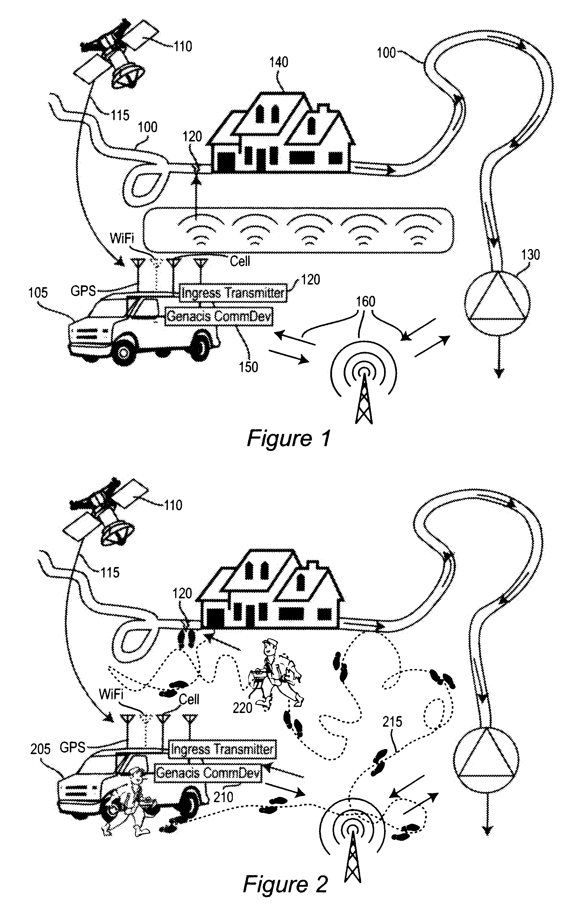
[0017]Referring now to the drawings, and more particularly to FIGS. 1 and 2, there is shown a graphical depiction of a detection or monitoring phase and a location and repair phase, respectively, of a method of detecting and remediating shielding flaws in a cable communication system, respectively. More specifically, in FIGS. 1 and 2, a representative portion of a cable communication system and its environment is illustrated including resources included in carrying out the method. Communication links are illustrated generally and schematically in FIGS. 1 and 2 but are illustrated in greater detail in FIG. 3.

[0018]While some particular elements of the cable communication system 100 and the individual resources employed in the method are known (although preferred resources which will be described below in connection with FIGS. 4 and 5 are not), the method in accordance with the invention is represented in the juxtaposition of those elements and resources and thus no portion of either ...


PUM


Abstract

Detecting ingress of a transmitted signal into a cable communication system due to a radio frequency signal transmitted from a moving vehicle and interrogation of transmitter location over a separate wireless link provides monitoring of shielding integrity or flaws there in a cable communication system. The location of a shielding flaw may then be precisely located in a closed loop fashion without risking overload of the cable communication system or interference with upstream signaling therein by detecting ingress signal strength and controlling transmitted signal strength while providing a user-perceptible indication of ingress signal strength which is compensated for the control of transmitted signal strength and thus indicates proximity of a hand-held instrument or transmitter to said shielding flaw.

Description

BACKGROUND OF THE INVENTION[0001]1. Field of the Invention[0002]The present invention generally relates to communication system condition monitoring and maintenance and, more particularly, to location of shielding faults in cable communication systems by detection of signal ingress into shielded cables of a cable communication system.[0003]2. Description of the Prior Art[0004]Cable communication systems for distribution of television programming and other data services are now familiar and popular in the United States. In recent years, so-called upstream signaling arrangements have also been provided on such systems for providing network (e.g. Internet) access for computers, interactive games and the like. Even more recently, it has been proposed to also provide telephone service over the same communication links as well and many cable service providers are implementing and actively marketing such an additional service.[0005]While such cable communications systems were initially imp...

Claims


Application Information

Patent Timeline
Patent Type & Authority Applications(United States)
IPC IPC(8): G01R31/08
CPCG01R31/083G01R29/0828
Inventor SHIMP, RICHARD L.ZIMMERMAN, DENNIS A.
Owner COMSONICS
Learn More