Method and device for synchronization of a decoder of a RFID receiver

Inactive Publication Date: 2010-02-04
TALLINN UNIVERSITY OF TECHNOLOGY +1
View PDF5 Cites 10 Cited by
  • Summary
  • Abstract
  • Description
  • Claims
  • Application Information

AI Technical Summary

Benefits of technology

[0008]The objective of the invention is to improve the synchronization speed and accuracy of the data-base for decoding of data bits, and so enabling to decode reliable decoding of the signals at lower signal-to-noise ratios, and so at increased distances or at smaller transmitted power. The objective is achieved by, in addition to finding a first correlation value by correlating the received input signal from the RFID tag with a first reference waveform (e.g., a preamble of the signal, a fragment of the preamble, or the preamble extended by following data bits), find

Problems solved by technology

One problem at RFID signal decoding is large tolerance of the bit-frequencies (up to 10%), which makes it difficult to decode reliably real signals containing noise and disturbances.
General disadvantage of the system is problem of exact finding of the beginning and ending of each data-bit and it will not allow reliable decoding of data bits at low signal-to-noise ratios being typical for real RFID systems, as power transmitted by readers is limited, and received signal is relatively weak.
So, the working distance of readers is lim

Method used


Image

  • Method and device for synchronization of a decoder of a RFID receiver
  • Method and device for synchronization of a decoder of a RFID receiver
  • Method and device for synchronization of a decoder of a RFID receiver

Examples


Example

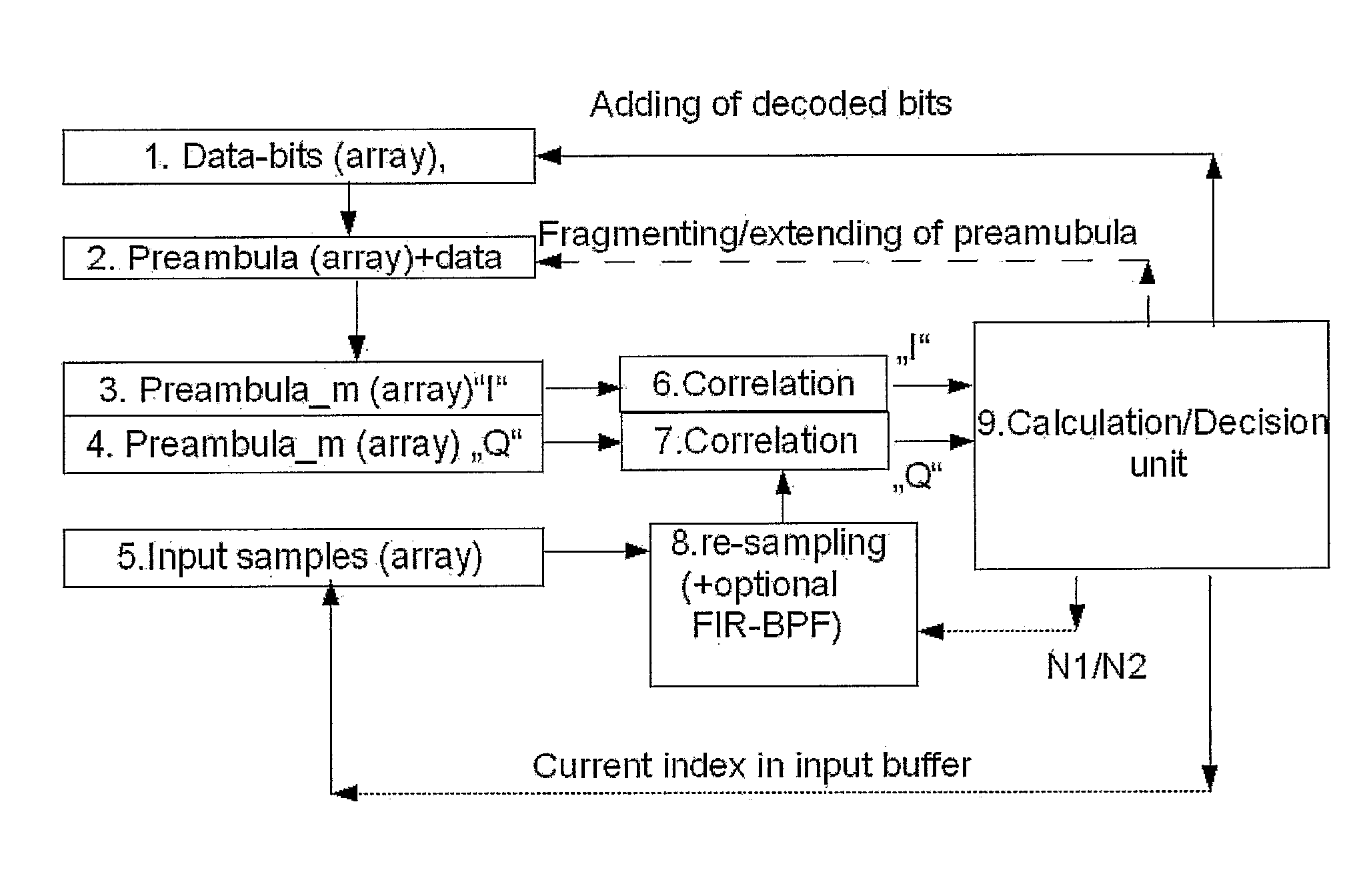
[0018]One embodiment of the invention contains two means for calculation of the correlation of the input signal, relatively to first and second reference waveforms, and, if the first correlation value is large enough, the second correlation value is used for further adjusting the synchronization of the timebase.

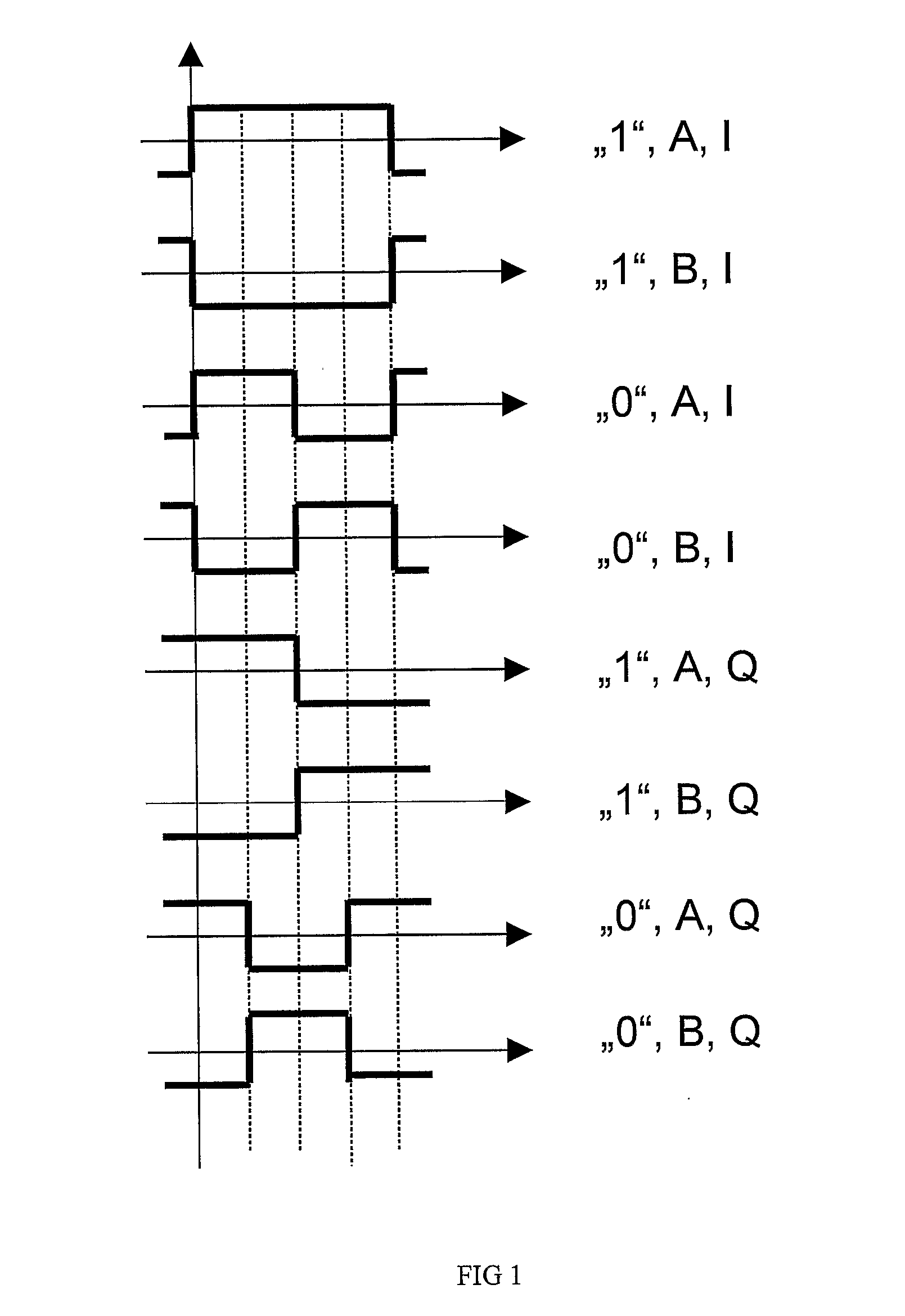
[0019]FIG. 1 depicts a first reference waveform and a second reference waveform, marked as “I” and “Q”, respectively, for different data-bit (“0″ and “1 “) and for two initial polarity values (“A” and “B”). So, to waveform fragment “1″, A, I of first reference signal corresponds a fragment “1″, A, Q of second reference signal, and for waveform fragment “1″, B, I of first reference signal corresponds a fragment “1″, B, Q of second reference signal, etc.

[0020]The first reference waveform “I” corresponds to a transmitted bit (symbol) and for ideal case (with no noise and disturbances), exact synchronization is achieved at the maximum correlation of first reference waveform and t...


PUM


Abstract

A method for synchronizing a RFID receiver, comprising receiving an input signal from a RFID tag, said input signal comprising a preamble section, creating a first reference waveform, comprising at least a fraction of said preamble section, calculating a first correlation value by correlating said input signal and said first reference waveform, creating a second reference signal so that there is virtually zero correlation between said first reference waveform and said second reference waveform, and using said first correlation value and said second correlation value for adjusting synchronization timebase, wherein the sign and the size of said second correlation value indicates the size and the sign of phase inaccuracy of the synchronization timebase.

Description

BACKGROUND OF THE INVENTION[0001]1. Technical Field[0002]The present invention relates to communication, more specifically to RFID (radio-frequency identification) systems, or similar, where decoding of bi-phase (for example FM0), Manchester or similar codes are needed. The main application field of the proposed invention are RFID-readers in RFID systems.[0003]2. Background Art[0004]RFID systems typically include RFID tags, and RFID readers (interrogators). Tags are mostly related to specific products or services, and are tracked by readers. Most often tags get power from the reader by radio frequency (RF) field, and respond to reader's commands by modulating the radio-waves. One problem at RFID signal decoding is large tolerance of the bit-frequencies (up to 10%), which makes it difficult to decode reliably real signals containing noise and disturbances.[0005]U.S. Pat. No. 6,501,807 “Data recovery system for radio frequency identification interrogator” describes a system where deco...

Claims


Application Information

Patent Timeline
IPC IPC(8): G08B13/14
CPCH04L7/042
Inventor MARTENS, OLEVKUUSIK, ALARLIIMETS, AIVAR
Owner TALLINN UNIVERSITY OF TECHNOLOGY
Why Eureka
Try Eureka