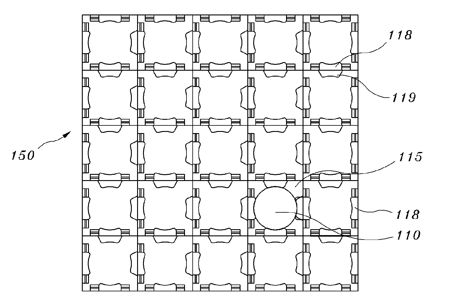
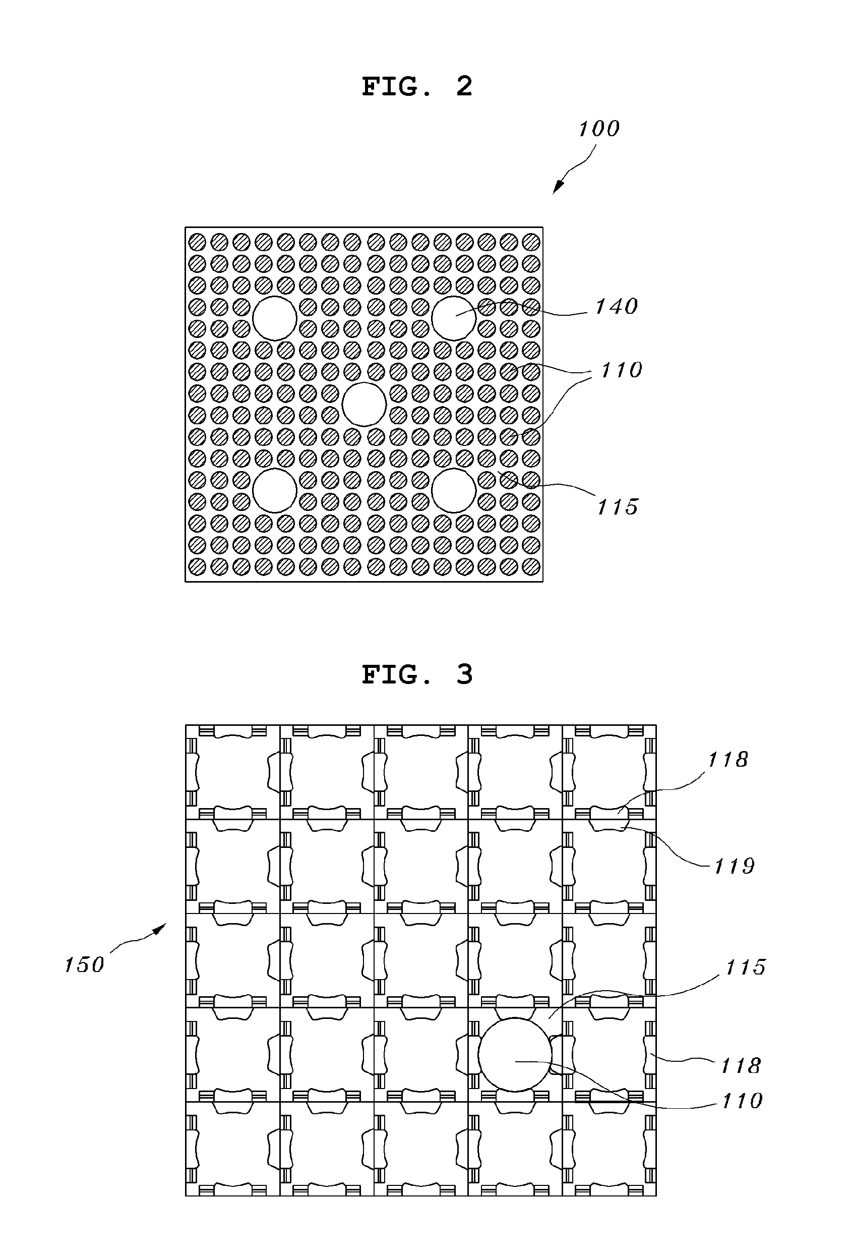
Spacer grid for dual-cooling nuclear fuel rods using intersectional support structures

a support structure and spacer grid technology, applied in nuclear engineering, nuclear elements, greenhouse gas reduction, etc., can solve the problems of increasing the temperature of nuclear fuel rods, and the inability to use the existing method of forming fuel rod support structures to realize contact, and achieve the effect of promoting impact strength

Active Publication Date: 2010-02-04
KOREA ATOMIC ENERGY RES INST
View PDF6 Cites 11 Cited by
  • Summary
  • Abstract
  • Description
  • Claims
  • Application Information

AI Technical Summary

Benefits of technology

[0031]Further, it is not necessary to change the positions of the guide pipes within the nuclear fuel assembly, and it is possible to use the top and bottom end pieces as they stand, so that the spacer grid can maintain compatibility with constituent parts of an existing nuclear fuel assembly without changing or modifying an existing reactor core structure.
[0032]In addition, the support structures are fitted into the grid straps around the intersections of the grid straps without performing plastic working on each grid strap to form the springs and dimples, so that the spacer grid can promote impact strength against lateral load.

Problems solved by technology

As a result, the heat generated from the nuclear fuel rods is not effectively transmitted to the coolant, thereby increasing the temperature of the nuclear fuel rods.
Thus, due to the narrow gap between the nuclear fuel rod and the unit grid strap, it is impossible to use the existing method of forming fuel rod support structures to realize contact at the portions where the fuel rod support structures intersect the nuclear fuel rods in order to support the nuclear fuel rods.

Method used


Image

  • Spacer grid for dual-cooling nuclear fuel rods using intersectional support structures
  • Spacer grid for dual-cooling nuclear fuel rods using intersectional support structures
  • Spacer grid for dual-cooling nuclear fuel rods using intersectional support structures

Examples


first embodiment

[0071]As illustrated in FIG. 10, each support structure 40, applied to the present invention, is provided with slits 41 at corners of a prism having a quadrilateral cross section so as to be coupled with the first fastening slits 22 and the second fastening slits 32.

[0072]At this time, the diagonal length of each support structure 40 must be equal to the interval between the first fastening slits 22 of each of the first grid straps 20 and the interval between the second fastening slits 32 of each of the second grid straps 30.

[0073]Specifically, in order to mutually couple the first grid straps 20 and the second grid straps 20 in a crossed state and then fit the support structures 40 into the first and second fastening slits 22 and 32 formed in the first and second grid straps, the diagonal length between the slits 41 formed in the corners of each support structure 40 in a diagonal direction must be equal to the transverse or longitudinal interval between the first fastening slits 22...

second embodiment

[0089]FIG. 15 illustrates a support structure applied to the present invention. The support structure 40 is provided with slits 41 in corners of a prism having a quadrilateral cross section so as to be coupled with the first fastening slits 22 and the second fastening slits 32, and concave supports 42 in faces thereof in the longitudinal direction so as to be in surface contact with the outer circumference of each dual-cooling nuclear fuel rod 10.

[0090]Further, each support 42 may be formed after cutting parts of upper and lower portions of each face of the support structure 40 in consideration of the rigidity of the support structure 40 or the fretting (or wear) characteristics of each dual-cooling nuclear fuel rod 10 resulting from the support structure 40.

[0091]In the case in which each support 42 has a concave shape, it is preferably adapted to have the same curvature as the outer circumference of each dual-cooling nuclear fuel rod 10 so as to be in surface contact with the oute...

third embodiment

[0100]FIG. 19 illustrates a support structure applied to the present invention. The support structure 40 is provided with four slits 41 in the circumference of a cylinder having a circular cross section at right angles so as to be coupled with the first fastening slits 22 and the second fastening slits 32, and supports 42, supporting the dual-cooling nuclear fuel rods 10 between the four slits 41.

[0101]At this time, the interval between the first slit 41 in the circumference of the support structure 40 and the third slit 41 facing the first slit in a diagonal direction must be equal to the interval between the first fastening slits 22 in each of the first grid straps 20 and the interval between the second fastening slits 32 in each of the second grid straps 30.

[0102]The supports 42 supporting the dual-cooling nuclear fuel rods 10 are arranged at four places on the circumference of the support structure 40 having the circular cross section at the same interval. Each support 42 includ...


PUM


Abstract

A spacer grid for dual-cooling nuclear fuel rods arranged at a narrow interval. The spacer grid solves the problem in which, since the dual-cooling nuclear fuel rods are used to improve the cooling performance and stability of nuclear fuel and obtain high burnup and output, the outer diameter of each dual-cooling nuclear fuel rod is increased, and thus the gap between each dual-cooling nuclear fuel rod and the grid strap is decreased. The spacer grid includes first grid straps and second grid straps, which are crossed and arranged in transverse and longitudinal directions at regular intervals and have the shape of a flat strip, and support structures, which are fitted into the first and second grid straps around intersections of the first and second grid straps so as to support the dual-cooling nuclear fuel rods.

Description

BACKGROUND OF THE INVENTION[0001]1. Field of the Invention[0002]The present invention relates, in general, to a spacer grid for dual-cooling nuclear fuel rods, which has been developed in order to reduce the core temperature of a nuclear fuel rod, thereby ensuring the safety of the nuclear fuel rod even at super high burnup, and increasing output to obtain economical effects and, more particularly, to a spacer grid for dual-cooling nuclear fuel rods using intersectional support structures, in which the intersectional support structures are fitted into grid straps around intersections of the grid straps in order to compensate for reduction in a gap between the nuclear fuel rod and the support structure due to an increase in diameter compared to an existing nuclear fuel rod, thereby supporting each dual-cooling nuclear fuel rod in a diagonal direction.[0003]2. Description of the Related Art[0004]FIG. 1 is a schematic perspective view illustrating a conventional nuclear fuel assembly. ...

Claims


Application Information

Patent Timeline
Patent Type & Authority Applications(United States)
IPC IPC(8): G21C3/34
CPCG21C3/02G21C3/322Y02E30/38G21C3/356G21C3/352Y02E30/30
Inventor KIM, JAE-YONGKIM, HYUNG-KYUYOON, KYUNG-HOLEE, YOUNG-HOLEE, KANG-HEE
Owner KOREA ATOMIC ENERGY RES INST
Why Eureka
Try Eureka