
Image processing unit, noise reduction method, program and storage medium

a noise reduction and image processing technology, applied in image enhancement, color signal processing circuits, instruments, etc., can solve the problems of inability to perform appropriate noise reduction suitable for neighboring edge structures (pixel value arrangement), image data picked up by image pick-up equipment such as scanners and digital cameras contain noise, etc., to achieve robust noise reduction results

Inactive Publication Date: 2010-02-04
RICOH KK
View PDF10 Cites 34 Cited by
  • Summary
  • Abstract
  • Description
  • Claims
  • Application Information

AI Technical Summary

Benefits of technology

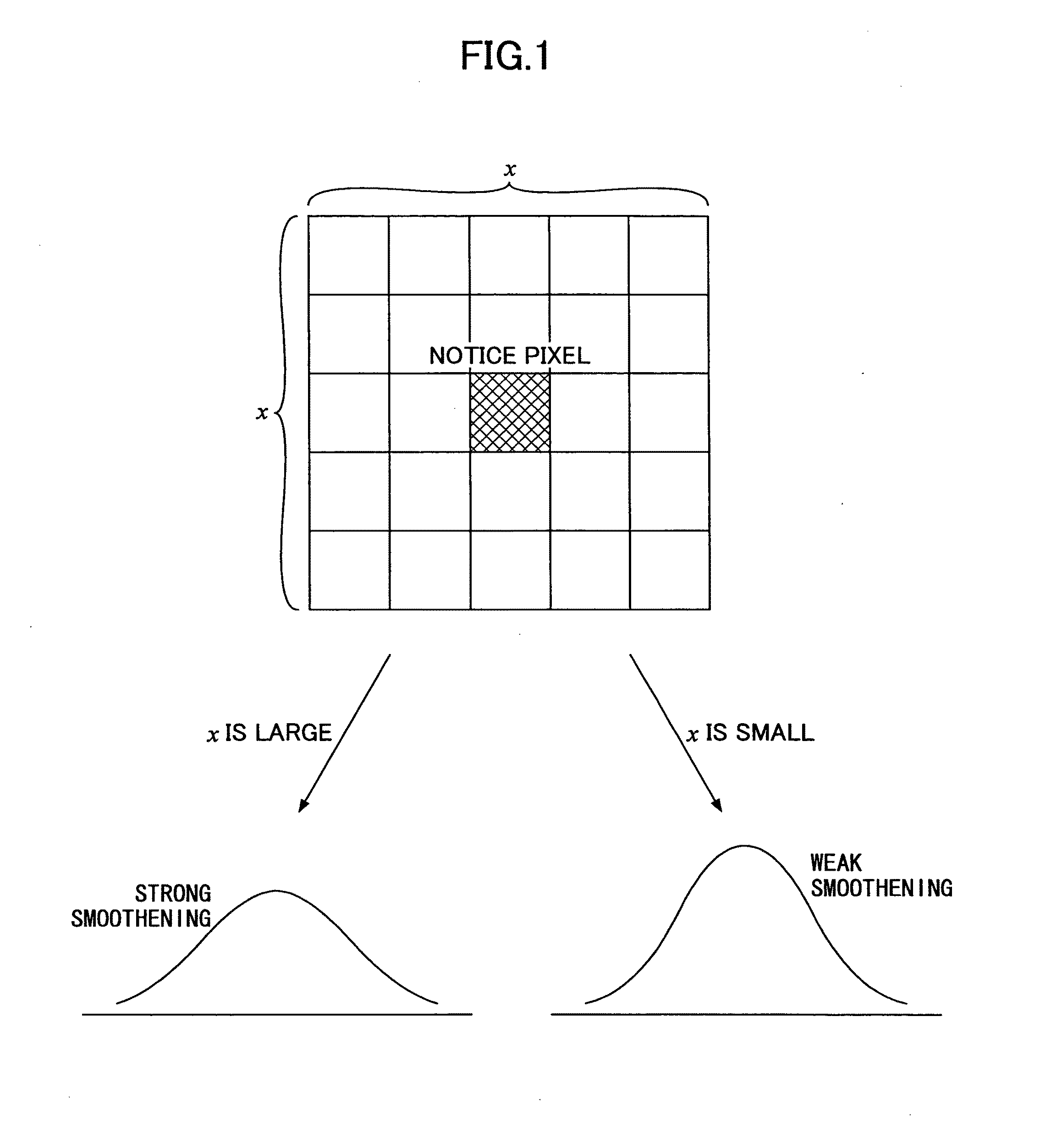
The present invention provides an image processing unit, a noise reduction method, a program, and a storage medium that can smoothly reduce noise in an image while maintaining edge extraction accuracy. The image processing unit uses pixel values from around a notice pixel to determine a region to be processed and smoothens the notice pixel accordingly. The noise reduction method includes extracting an edge, determining a region to be processed, and changing the smoothening intensity based on the size of the region to be processed. The program and storage medium allow for the efficient and effective reduction of noise in images.

Problems solved by technology

In many cases, image data picked up by image pick-up equipment such as scanners and digital cameras contain noise due to the characteristics of image pick-up devices, such as a dark current and a residual current.
However, even if a low-pass filter or the like is used to simply reduce the noise, an important element such as an edge necessary for humans to perceive is blurred, which results in degradation of image quality.
However, since the technologies disclosed in Patent Documents 1 through 3 do not use edge information in the vicinity of a pixel to be processed (a notice pixel), appropriate noise reduction suitable for a neighboring edge structure (arrangement of pixel values) cannot be performed.
Furthermore, since edge information is generally extracted from an image from which noise has not been eliminated, it is not possible to assure that all the edge information is correct.
Accordingly, as described in Patent Document 2 through 4, if the edge cannot be correctly extracted when noise is eliminated at one pixel position where edge information is detected, degradation of image quality, such as excessive edge blurring or insufficient noise reduction, occurs.

Method used


Image

  • Image processing unit, noise reduction method, program and storage medium
  • Image processing unit, noise reduction method, program and storage medium
  • Image processing unit, noise reduction method, program and storage medium

Examples


first embodiment

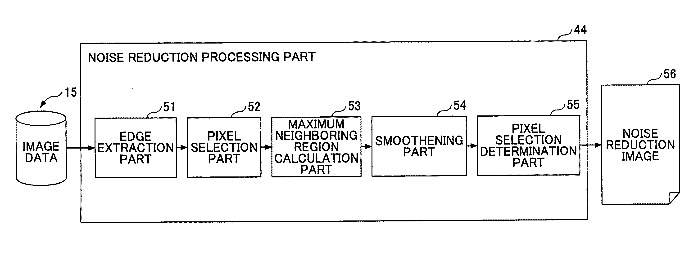
[0061]This embodiment refers to the image processing unit 100 that searches for a neighboring region with a notice pixel as a center so as to form a rectangular shape and represents the area of a maximum neighboring region, where the sum of obtained edge intensities exceeds a threshold, on the variance parameter of a Gaussian filter to perform smoothening processing.

[0062]The neighboring region is composed of one or more neighboring pixel regions including the notice pixel and is formed into a rectangle in this embodiment. Furthermore, the maximum neighboring region is a neighboring region where the sum of edge intensities exceeds a threshold. Therefore, if the edge intensity of the notice pixel is greatly changed, one pixel could form the maximum neighboring region at minimum. On the other hand, if the edge intensities of neighboring regions of the notice pixel are small, the maximum neighboring region becomes large.

[0063]FIG. 4 is an example of a functional block diagram of the no...

second embodiment

[0090]In the first embodiment, n is increased in increments of two so as to find the maximum neighboring region. However, according to this method, the smoothening intensity may not be finely adjusted in some cases because the size of the neighboring region is discretely changed. In view of this problem, this embodiment refers to the image processing unit 100 that can specifically calculate the size of the maximum neighboring region by using an interpolating method.

[0091]Note that similar to the first embodiment, this embodiment uses the functional block diagram of the noise reduction processing part 44 shown in FIG. 4 and the flowchart shown in FIG. 5. This embodiment is characterized by step S104 in the flowchart.

[0092](S104)

[0093]The maximum neighboring region calculation part 53 finds the sum of the edge intensities E in the rectangle of “n×n” pixel regions with the notice pixel as a center. Similar to the first embodiment, the maximum neighboring region calculation part 53 star...

third embodiment

[0101]In the first and second embodiments, the maximum neighboring region is determined based on only the edge intensities E, and the size of the maximum neighboring region is used in the variance parameter of the Gaussian filter. This embodiment refers to the image processing unit 100 that can include the direction of the edges on the Gaussian filter.

[0102]Note that similar to the first embodiment, this embodiment uses the functional block diagram of the noise reduction processing part 44 shown in FIG. 4 and the flowchart shown in FIG. 5. This embodiment is characterized by the smoothening processing in step S105 in the flowchart.

[0103](S105)

[0104]The direction of the edges (hereinafter referred to as an edge direction θ) is set based on, for example, a horizontal direction (zero degrees) as a reference. In this case, the edge direction θ of the edges successively arranged in a vertical direction is set at 90 degrees, and the edge direction θ of the edges successively arranged in t...


PUM


Abstract

An image processing unit is disclosed that smoothens a notice pixel of input image data with pixel values of pixels around the notice pixel to reduce noise in the image data. The image processing unit includes an edge extraction unit that extracts an edge based on the pixel values of the image data; a region determination unit that determines a region to be processed where a sum of edge intensities of the pixels including the notice pixel becomes greater than or equal to a threshold; and a smoothening unit that changes a smoothening intensity in accordance with a size of the region to be processed to smoothen the notice pixel corresponding to the region to be processed.

Description

BACKGROUND OF THE INVENTION[0001]1. Field of the Invention[0002]The present invention relates to an image processing unit, a noise reduction method, a program, and a recording medium for reducing noise of image data.[0003]2. Description of the Related Art[0004]In many cases, image data picked up by image pick-up equipment such as scanners and digital cameras contain noise due to the characteristics of image pick-up devices, such as a dark current and a residual current. Therefore, processing for reducing the noise is required. However, even if a low-pass filter or the like is used to simply reduce the noise, an important element such as an edge necessary for humans to perceive is blurred, which results in degradation of image quality. In view of this problem, technologies for processing noise for each region in accordance with the characteristics of each region of image data have been proposed (see, for example, Patent Document 1 through 4).[0005]Patent Document 1 discloses an image...

Claims


Application Information

Patent Timeline
Patent Type & Authority Applications(United States)
IPC IPC(8): G06K9/40
CPCG06T2207/20012G06T2207/20192G06T7/0085G06T5/002G06T5/20H04N1/409G06T7/13G06T5/70
Inventor HARA, TAKAYUKIGUAN, HAIKEHIKIDA, SATOSHI
Owner RICOH KK
Learn More