
Panel-form loudspeakers

a loudspeaker and panel technology, applied in the field of acoustic devices, can solve the problem that the size of the affixed mass should not exceed the acceptable compromis

Inactive Publication Date: 2003-02-11
NEW TRANSDUCERS LTD
View PDF11 Cites 29 Cited by
  • Summary
  • Abstract
  • Description
  • Claims
  • Application Information

AI Technical Summary

Benefits of technology

Such a hole through the panel member within the area of the driver, typically voice coil coupling removes panel material which could otherwise resonate in drum-like manner. Such a hole also militates against what could otherwise effectively be stiffening by the driver coupling. Efficiency of power transfer into the panel member may be usefully increased. Reduction of mass of the panel member near the voice coil, and the presence of an "edge" within the excitation area can assist bending wave formation and acoustic radiation, with effective reduction of unwanted high frequency content from drumming effects. Diffraction resulting from such a hole / edge can be reduced by various means including extending the drive unit pole piece into the hole, or adding other material to the pole piece, say to make it level with the panel surface.
Such a hole can allow the possibility of fixing the voice coil former right through the panel member, skin-to-skin, to increase the strength of fixing bond and to allow higher powers to be applied to the panel member without damaging the structure.
Suitable apertures or holes in the panel member, particularly through the area of driver coupling thereto, may range up to cross-sectional size of the vibration-inducing driver component, usually voice coil. Different hole sizes produce different upward shifts of unwanted high frequencies arising from drumming, thus enable extension of acoustic working frequency range to desired extent of reduction of intrusion / content from drum-like vibration.
Suitable affixed mainly mass-effective means, which may be small, typically fraction of a gram, will serve as a load that reduces efficiency of bending involved in drum-like vibration, thus at least reducing amplitude of unwanted high frequency acoustic components of drumming. Size of the affixed mass should not be more than achieves acceptable compromise between desired reduction of unwanted high frequencies and inevitable accompanying reduction of adjacent wanted frequencies.
There is another advantageous use for typically similarly small added / affixed masses in the control of otherwise at least potentially overly excited acoustic output frequencies, namely at feasible but unused in-board preferential driver coupling locations, with the useful effect for the acoustic output of the panel member that it is beneficially quieted and smoother. This is, of course, applicable both with and without other control(s) hereof in relation to drumming, and thus of independent inventive merit.

Problems solved by technology

Such a hole also militates against what could otherwise effectively be stiffening by the driver coupling.
Size of the affixed mass should not be more than achieves acceptable compromise between desired reduction of unwanted high frequencies and inevitable accompanying reduction of adjacent wanted frequencies.

Method used


Image

  • Panel-form loudspeakers
  • Panel-form loudspeakers
  • Panel-form loudspeakers

Examples


Embodiment Construction

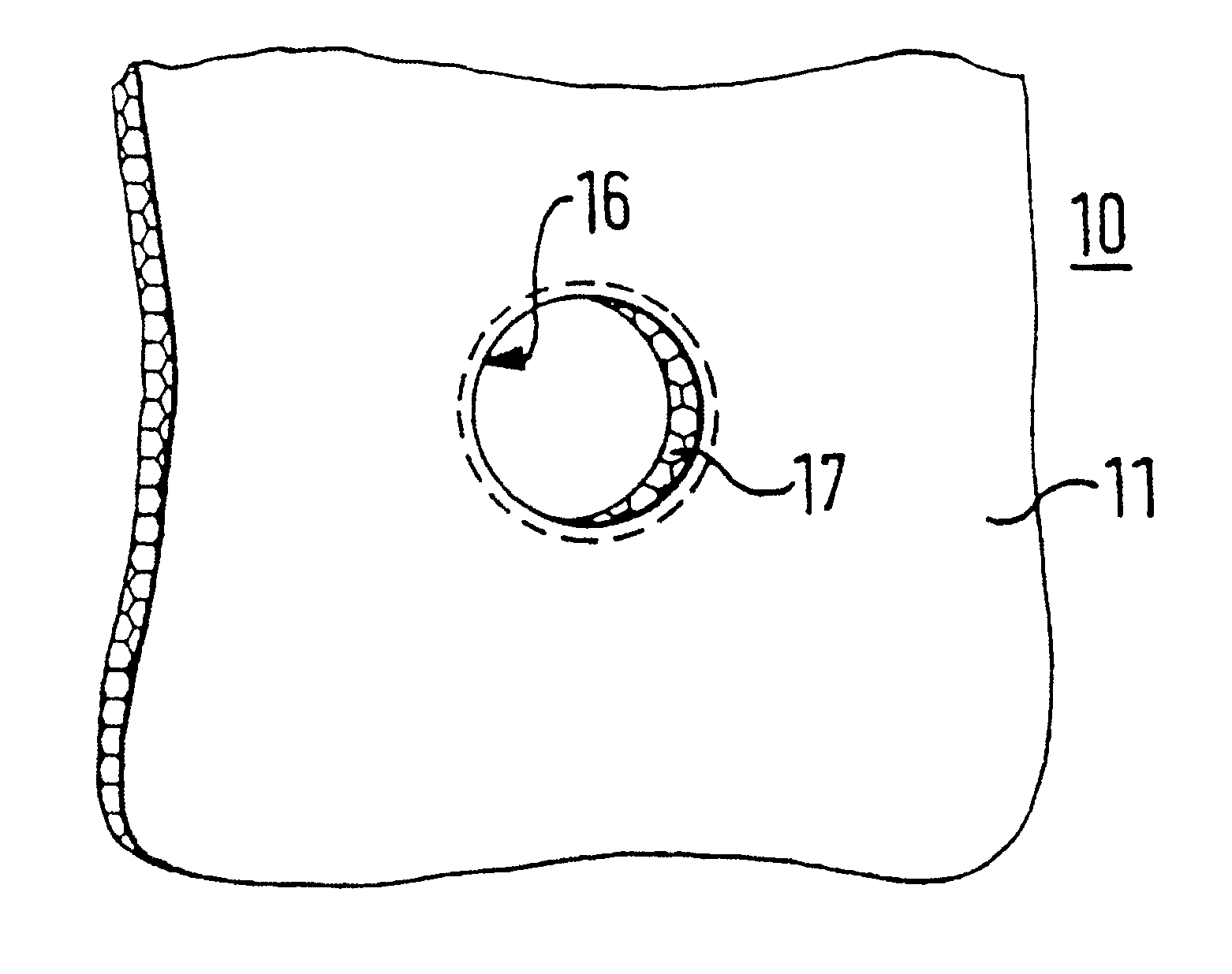
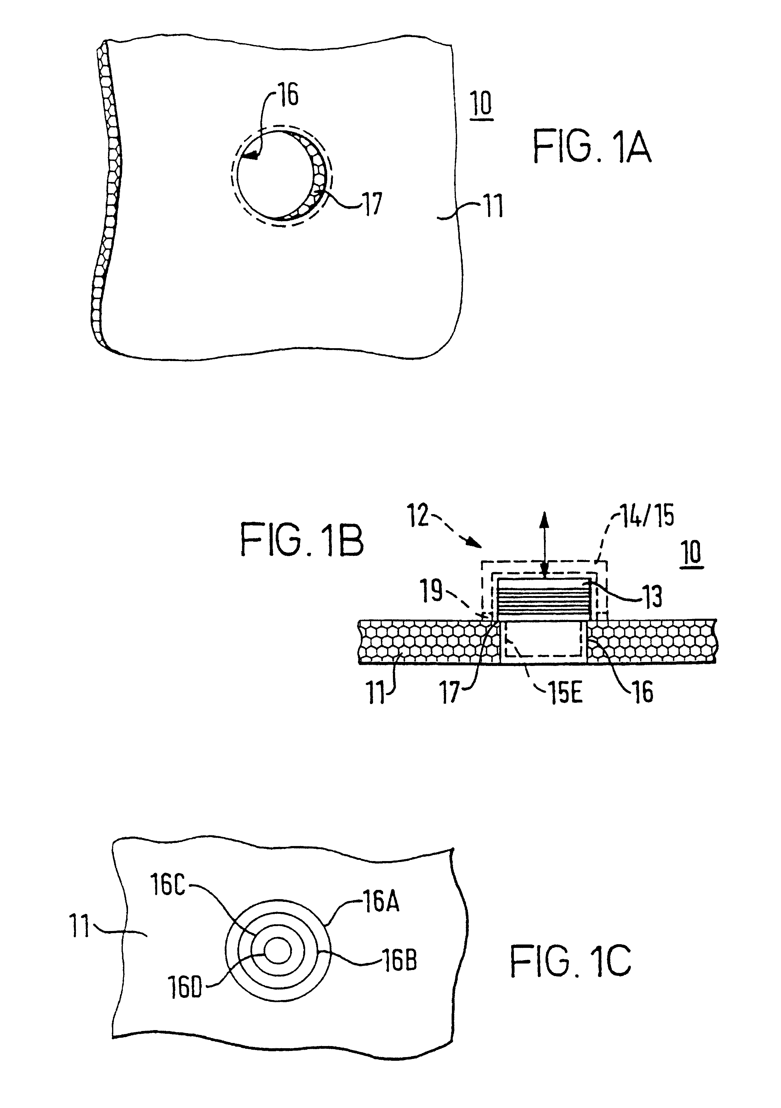
In FIGS. 1A, B, C loudspeaker 10 has a panel member 11 with a magnet-and-moving coil type driver 12 coupled thereto for causing bending wave action and corresponding acoustic output according to driver energisation. The driver 12 is shown with its moving voice coil 13 connected end-on to the panel member 11 for reciprocation relative to the magnet and pole-piece assembly 14 / 15 of the driver 12, thus push-pull action in launching bending wave in the panel member 11. The panel member 11 is shown with a parallel-sided through-hole 16 and the voice coil 13 on a peripheral margin 17 about the hole 16. FIG. 1B has dashed indication 15E of pole-piece 15 extended partially into the hole 16. FIG. 1C has indications of different hole sizes 16A, B, C, D corresponding to less than the full matching of area within confines of the voice coil 13.

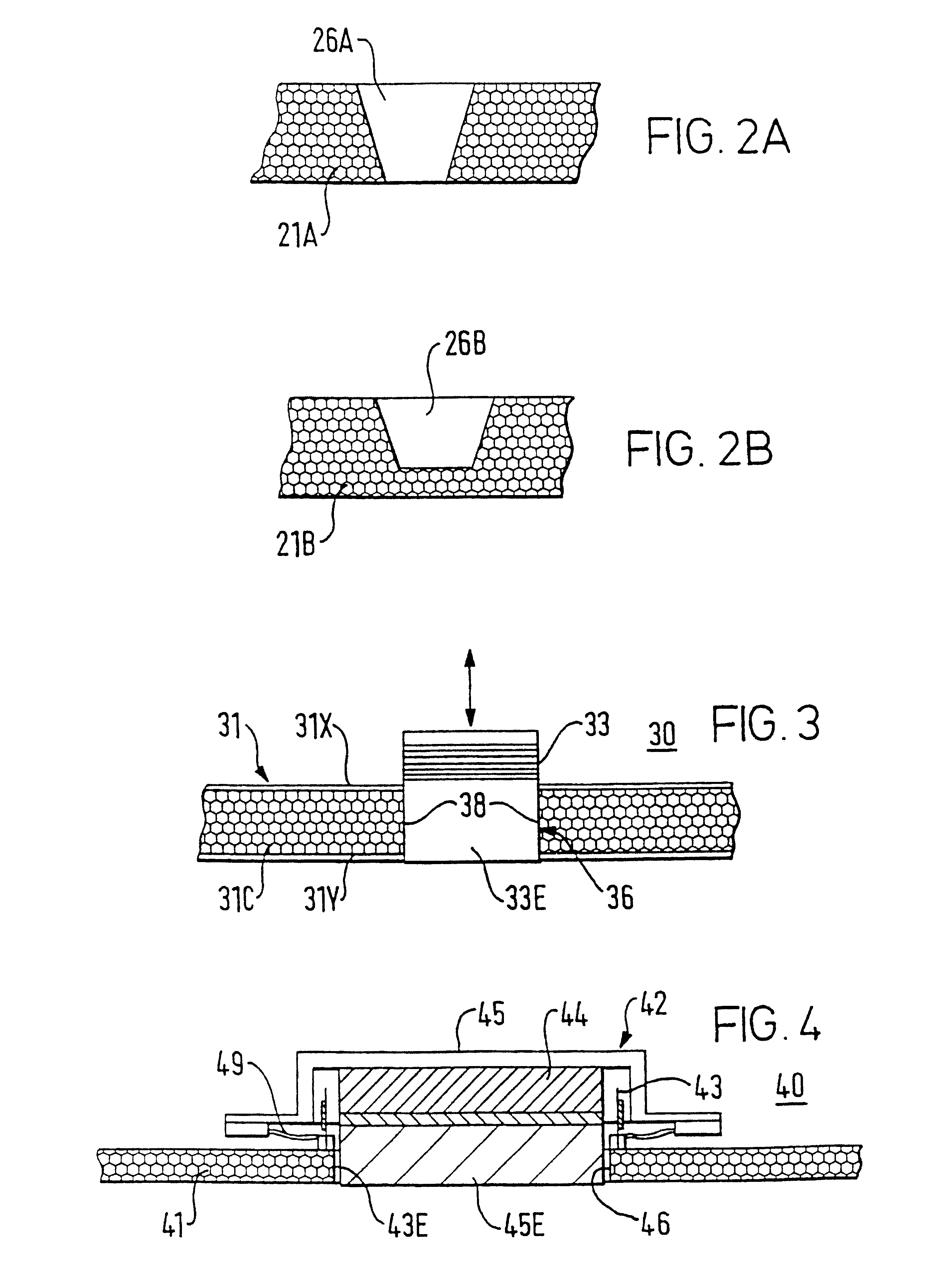
FIGS. 2A and 2B show variant aperturing of the panel member 21 as tapered through-hole 26A and tapered blind hole 26B respectively. Generally, holes local...


PUM


Abstract

A loudspeaker comprises a panel member (11, 21, 31, 41, 61, 71, 81, 91) as resonant acoustic radiator relying on bending wave action and a driver (12, 22, 32, 42, 62, 72, 82, 92) coupled to the panel member to cause bending waves therein. The panel member has its mass and / or bending capability of the panel member locally altered or otherwise different, particularly locally of the driver as coupled to the panel member. Local holes (16, 26, 36, 46), affixed mass (66) or affixed damping material (76) are effective to reduce high frequency due to drumming effects at the driver coupling (17, 37, 47, 67, 77, 87).

Description

DESCRIPTIONField of the InventionThis invention relates to acoustic devices for which acoustic performance relies on bending wave action and related beneficial areal distribution of resonant modes of surface vibration.For first teaching regarding such resonant mode acoustic devices, particularly as panel-form members, reference is directed to International Patent Application WO97 / 09842; or its U.S. equivalent, application Ser. No. 08 / 707,012, filed Sep. 3, 1996 and various later patent applications by New Transducers Limited before this patent application make useful additions and developments, including as to viable variations of transducer location(s) and / or panel distribution(s) of bending structure / geometry and / or stiffness and / or mass.This invention arises particularly in relation to loudspeakers using such panel-form members as acoustic radiators.BACKGROUND TO THE INVENTIONA typical panel-form loudspeaker comprises a distributed mode acoustic radiation member having a moving c...

Claims


Application Information

Patent Timeline
Patent Type & Authority Patents(United States)
IPC IPC(8): H04R7/00H04R9/00H04R7/04H04R9/06H04R7/06
CPCH04R9/066H04R7/045H04R9/06
Inventor MORECROFT, DENISHARRIS, NEIL
Owner NEW TRANSDUCERS LTD
Learn More