
Abdominal aortic aneurysms: systems and methods of use

a technology systems, applied in the field of abdominal aortic aneurysms : systems and methods of use, can solve the problems of high longitudinal force, high deployment force, and severe compression of very large stents into small diameter tubes or lumens, so as to avoid complications and death, accurate control of the graft system

Active Publication Date: 2010-02-04
BOLTON MEDICAL INC
View PDF118 Cites 137 Cited by
  • Summary
  • Abstract
  • Description
  • Claims
  • Application Information

AI Technical Summary

Benefits of technology

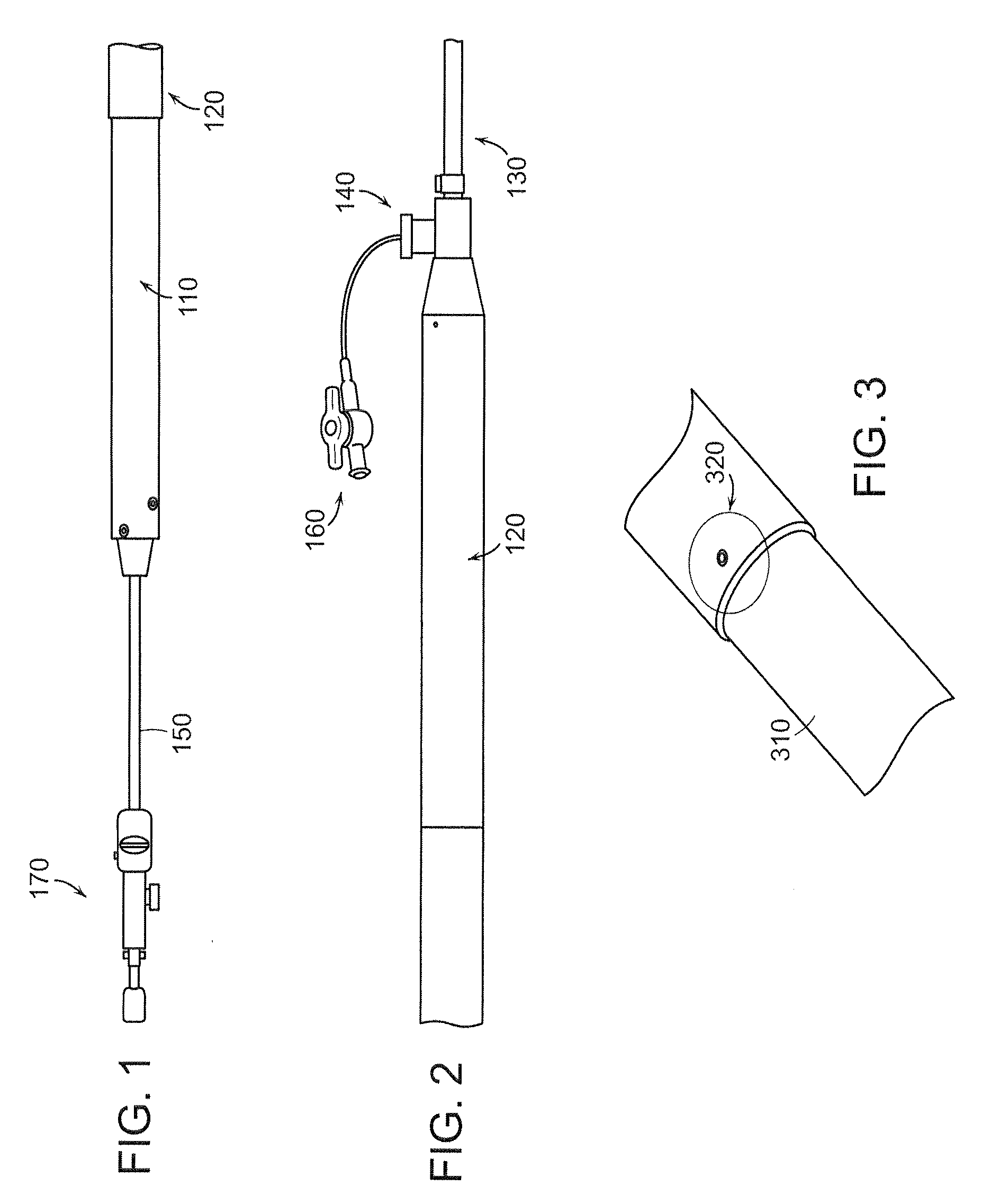
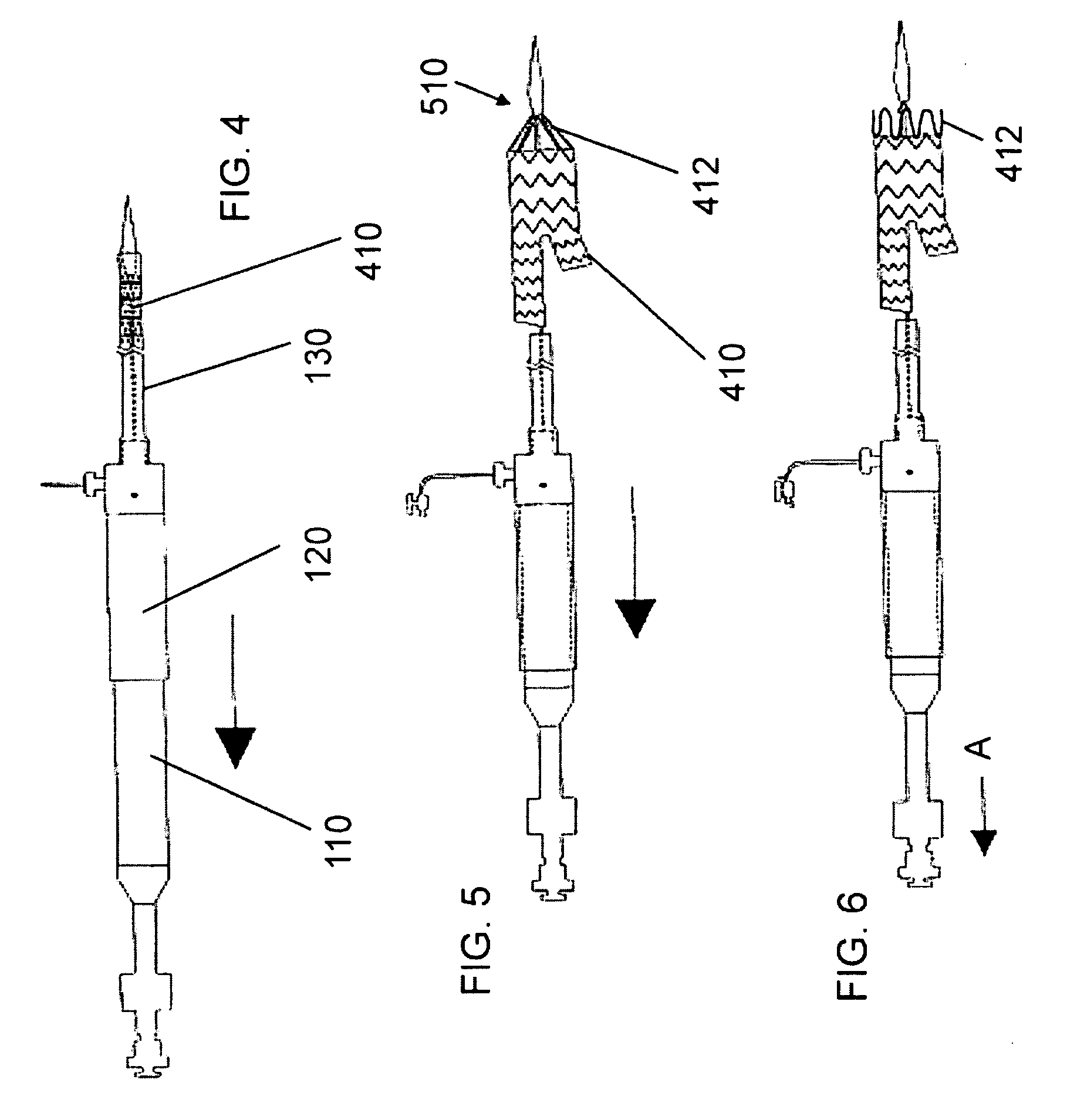
[0029]Benefits achieved by the invention are represented, for example, by FIGS. 1 to 15, specifically FIGS. 15A, 15B, and 15C. Current pin-and-pull systems have an undesired force to the inner stabilizing member during deployment because there is a tendency to flex where gripped thereon (see FIGS. 15A and 15B). This flexing caused misalignment of the sheath hub and the inner stabilizing member, which, in turn, required the physician to increase deployment forces for retracting the outer sheath, thus, correspondingly increasing the force against the inner stabilizing member (a damaging cycle). The telescopic systems of the invention, in contrast, offer protection of the inner stabilizing member because the force is not directly applied to the inner stabilizing member. The two-rigid-tube telescopic system of the invention incorporates two hard surfaces that retract on one another over the inner stabilizing member and, thereby, reduce any chance of buckling of the inner stabilizing member. During the retraction process, the force is transmitted uniformly over the inner stabilizing member.
[0030]By creating a mechanical interaction, the modular pull out force can exceed clinical requirements. Modular disassociation creates serious type III endoleaks, which can have significant clinical consequences. This type of securement significantly reduces the likelihood of this event. Also, this system does not require rotational alignment between the receiving and inserting components. This makes the mechanism substantially invisible to the doctor and does not add any complexity to the procedure. Further, the system prevents adverse complications during the procedure. By using a proximally facing fold in the graft, there is virtually no chance of accidental ensnarement of a guide wire during the procedure. If loops or holes were placed in the first member, then a guidewire could potentially get caught without the physician being aware of that ensnarement.
[0032]In addition, barbs located at suprarenal and infrarenal positions, may provide positive fixation and the leg clasp of the invention may provide for accurate control of the graft systems during cannulation and placement of the graft system in the vasculature.
[0033]Thus, the delivery systems, components of delivery systems and methods of the invention can be used to treat AAA and, therefore, avoid complications and death consequent to life threatening vascular conditions.

Problems solved by technology

This usually results in severe compression of very large stents into small diameter tubes or lumens.
The drastic inward compression results in high longitudinal forces for loading the stent graft—pushing the pre-compressed stent into the delivery system sheath—and in high deployment forces—occurring when the stent graft is unsheathed at the time of clinical deployment.
High deployment forces reduce a physician's ability to control deployment accuracy.
Other factors can adversely affect deployment accuracy and present additional problems that the physician must address or for which the physician must compensate.
Once the user has overcome the initial friction between the sheath and the compressed stent, the force then needed for deployment plummets.
This rapid decline is almost instantaneous and, often, the physician is not able to react quickly enough to lower the force being supplied to the delivery system.
This failure to react results in deployment of more of the stent graft than intended by the physician or in a deployment that fails to hit the intended target site (i.e., low deployment accuracy).
Modular disassociation creates serious type III endoleaks, which can have significant clinical consequences.
This type of securement significantly reduces the likelihood of this event.
(If loops or holes were placed in the first member, then a guidewire could potentially get caught without the physician being aware of that ensnarement.)
Moreover, the folds in the graft create extra layers of material.
Significantly, by having multiple engaging members of the second (inserting) stent graft, there is redundancy in the vessel repair system.

Method used


Image

  • Abdominal aortic aneurysms: systems and methods of use
  • Abdominal aortic aneurysms: systems and methods of use
  • Abdominal aortic aneurysms: systems and methods of use

Examples


Embodiment Construction

[0161]The features and other details of the invention, either as steps of the invention or as combinations of parts of the invention, will now be more particularly described and pointed out in the claims. It will be understood that the particular embodiments of the invention are shown by way of illustration and not as limitations of the invention. The principle features of this invention can be employed in various embodiments without departing from the scope of the invention.

[0162]In an embodiment, represented by FIGS. 1 through 57, as an example, the invention is a stent graft delivery system 5500, comprising a handle that includes distal grip 5530 and handle body 5540 extending from one end of distal grip 5530, the handle defining conduit and track 5542 along a portion of the length of distal grip 5530 and handle body 5540; an internal lead screw assembly 5510 within the conduit, the internal lead screw assembly 5510 being moveable along a major axis of the conduit, and including ...


PUM


Abstract

Delivery systems, components of delivery system, stent graft systems, stent graft delivery systems can be used to treat aortic aneurysms.

Description

RELATED APPLICATIONS[0001]This application claims the benefit of U.S. Provisional Application No. 61 / 077,031, filed on Jun. 30, 2008, and U.S. Provisional Application No. 61 / 164,545, filed on Mar. 30, 2009.[0002]The entire teachings of the above applications are incorporated herein by reference.BACKGROUND OF THE INVENTION[0003]Stent graft delivery systems have been designed to treat abdominal aortic aneurysm (AAA) to minimize the diameter or “French” size of the portion to be inserted into the patient. This usually results in severe compression of very large stents into small diameter tubes or lumens. The drastic inward compression results in high longitudinal forces for loading the stent graft—pushing the pre-compressed stent into the delivery system sheath—and in high deployment forces—occurring when the stent graft is unsheathed at the time of clinical deployment. Other factors cumulatively add to this deployment force including, for example, friction between components of the de...

Claims


Application Information

Patent Timeline
IPC IPC(8): A61F2/01A61F2/06
CPCA61F2/07A61F2220/0016A61F2/95A61F2/966A61F2002/8483A61F2002/9505A61F2002/9517A61F2002/9665A61M39/06A61F2/848A61F2/89A61F2220/0041A61F2220/0075A61F2230/0054A61F2210/0076A61F2220/0008A61F2/91A61F2002/075A61F2002/9511A61F2210/0014A61F2/9517A61F2/064
Inventor BERRA, HUMBERTOWHITE, BRYANLOSTETTER, TIMOTHYRUSH, SCOTT LYLECANNING, JOHN C.
Owner BOLTON MEDICAL INC
Learn More