
Flow rate ratio control device

a flow rate ratio and control device technology, applied in water supply installation, process and machine control, instruments, etc., can solve the problems of unstable inability to reach the target pressure, and considerable time, so as to improve the control response, shorten the control stop period of the control valve, and improve the transient performance of branch flow control

Active Publication Date: 2010-02-04
HORIBA STEC CO LTD
View PDF2 Cites 33 Cited by
  • Summary
  • Abstract
  • Description
  • Claims
  • Application Information

AI Technical Summary

Benefits of technology

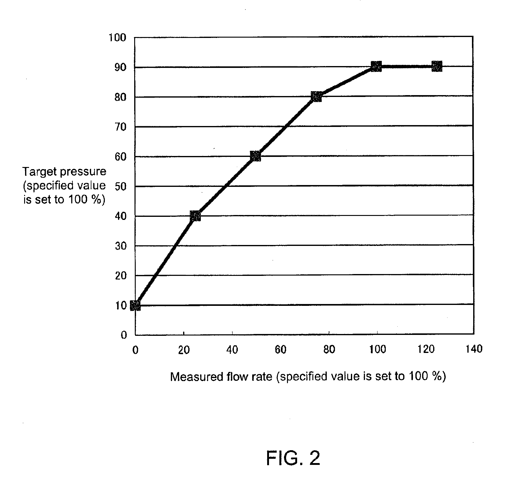
[0017]According to the present invention configured as described above, even if a total flow rate of introduced fluid is small, a target pressure is changed and set lower depending on the small flow rate, and therefore a measured pressure quickly reaches near or not less than the target pressure. As a result, a control stop period of a control valve can be shortened, and even in the case of a small flow rate, control response is improved as compared with the conventional case, and therefore transient performance of branch flow control can be improved.

Problems solved by technology

However, a problem with such devices is that in a state where the flow rate through the main flow channel RXM is small, the response becomes poor, and therefore transient performance of the branch flow control becomes unstable.
However, because of the low flow rate, the pressure only gradually rises, and therefore it takes time to reach the target pressure.
It turns out that once the pressure has dropped (at time TS), in a state where the flow rate is low, it takes a considerable period of time (t1) until the pressure is recovered, during which interval the control is unstable.
That is, as described above, if the flow rate through the main channel is decreased, the device response becomes poor, and therefore performance of branch flow control in the transient situation is deteriorated.

Method used


Image

  • Flow rate ratio control device
  • Flow rate ratio control device
  • Flow rate ratio control device

Examples


Embodiment Construction

[0024]One embodiment of the present invention will hereinafter be described referring to the drawings.

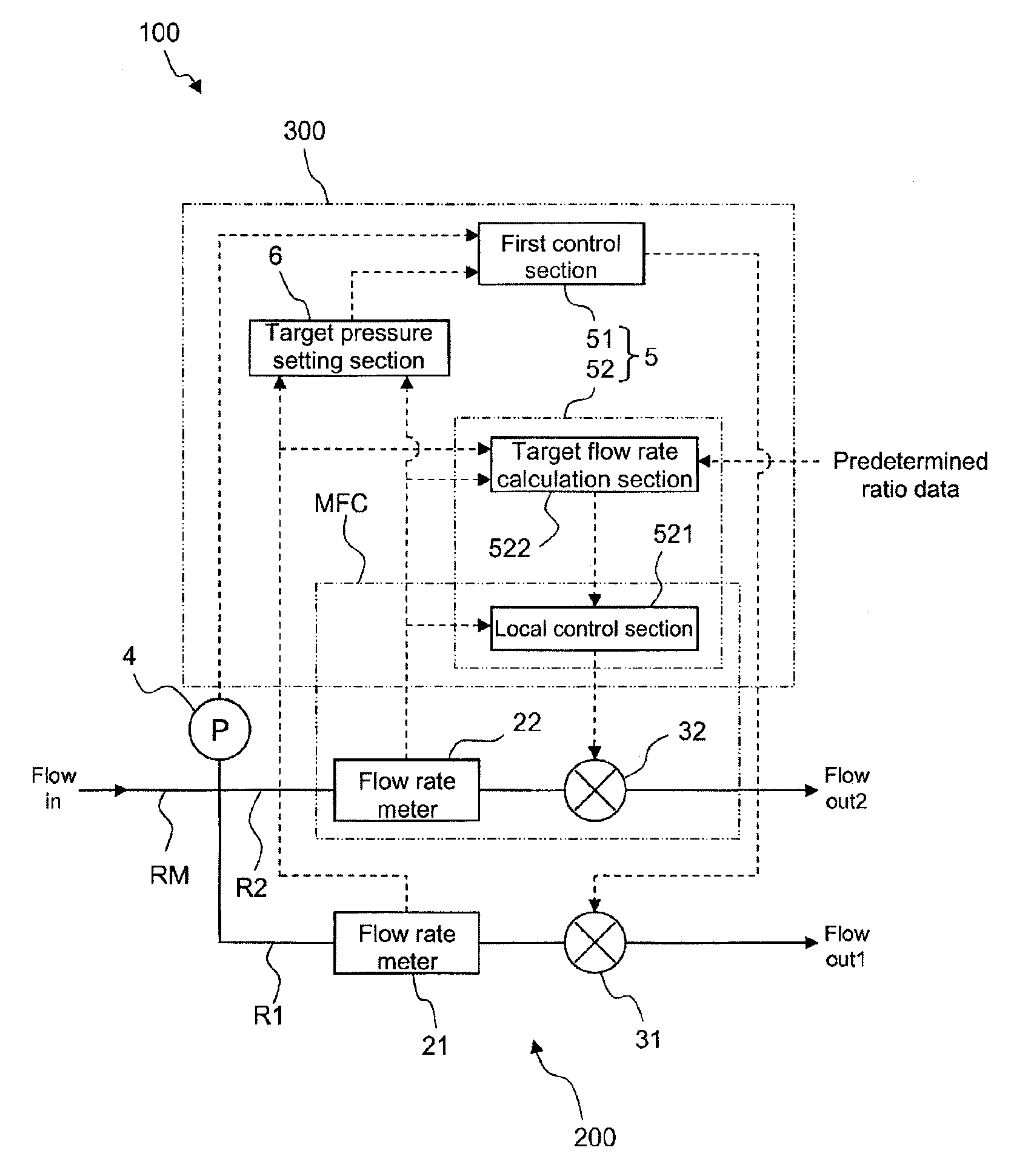
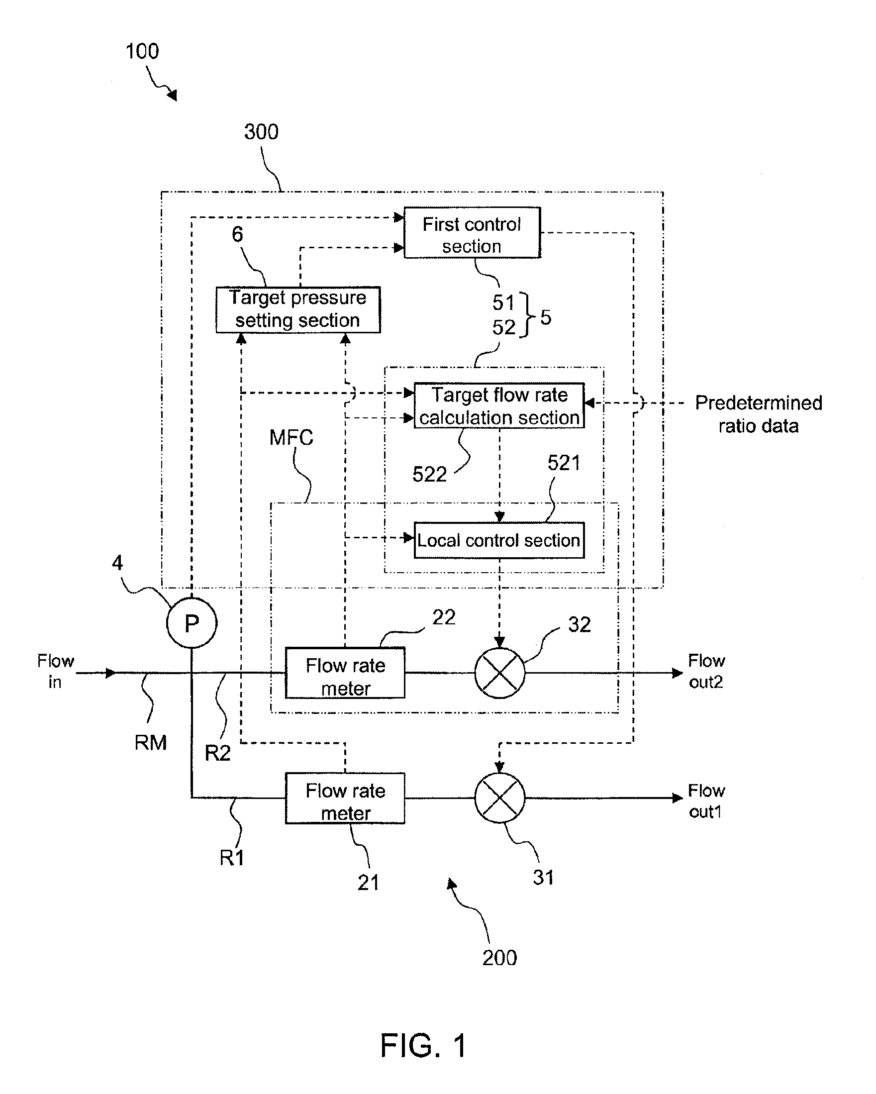
[0025]FIG. 1 is a schematic diagram illustrating a flow rate ratio control device 100 according to the present embodiment. The flow rate ratio control device 100 is a device for branching a flow of, for example, source gas for semiconductor manufacturing at a predetermined ratio to supply the gas to a semiconductor processing chamber, and constitutes a part of an unshown semiconductor manufacturing system. The device 100 mainly includes a fluid circuit mechanism 200, and a control mechanism 300 for controlling the fluid circuit mechanism 200.

[0026]The fluid circuit mechanism 200 is a mechanism having the same configuration as that of the above-described conventional device, and includes a main channel RM into which fluid to be branched flows, and two branch channels R1 and R2 that branch from an end part of the main channel RM. The fluid to be introduced into the main channel RM is,...


PUM


Abstract

A flow rate ratio control device having: a main channel (RM); branch channels (R1, R2) branching from the end of the main channel (RM); control valves (31, 32) respectively provided in the branch channels (R1, R2); flow rate measurement means for measuring the flow rate of the main channel (RM) and the flow rate of each of the branch channels (R1, R2); a valve control section (5) for controlling the a control valve (31) provided in one branch channel (R2) so that the pressure on the upstream side of the control valve (31) is a given target pressure and, only when the upstream-side pressure is near or not less than the target pressure, starting control of the other control valve (32) so that the flow rate ratios of the branch channels (R1, R2) are predetermined ratios; and a target pressure setting section (6) for setting the target pressure such that the smaller the flow volume is in the main channel (RM), the lower is the target pressure.

Description

BACKGROUND OF THE INVENTION[0001]1. Field of the Invention[0002]The present invention relates to flow rate ratio controllers, used in semiconductor manufacturing processes, which branch at a desired ratio a flow of source gases.[0003]2. Description of the Background Art[0004]In the field of the semiconductor manufacturing process in recent years, along with an increase in wafer size, the size of the processing chambers containing the wafers has also been increased. Meanwhile, when films are deposited on semiconductor wafers, the source gases for the deposition preferably have a uniform concentration; however, if the source gases are introduced into one of these larger-sized processing chambers through only one location, the concentration distribution may become partially unbalanced.[0005]For this reason, more recently, processing chambers have been adapted so as to incorporate a plurality of gas inlets, and fed through the respective inlets with source gases at a mass flow ratio tha...

Claims


Application Information

Patent Timeline
Patent Type & Authority Applications(United States)
IPC IPC(8): G05D11/13G05D7/06
CPCG05D11/132G05D7/0664Y10T137/7759Y10T137/0363Y10T137/7761Y10T137/87772G05D11/00G05D11/02
Inventor YAMAGUCHI, YUJIMATSUMOTO, AKIHIROYONEDA, YUTAKA
Owner HORIBA STEC CO LTD
Learn More