
Collision avoidance device

a technology of collision avoidance and collision probability, which is applied in the direction of anti-collision systems, non-deflectable wheel steering, underwater vessels, etc., can solve the problems of increasing unnecessary collision avoidance control, deteriorating traveling stability, and many unnecessary warnings, so as to prevent accurately judge collision probability, and avoid wasteful collision avoidance control

Active Publication Date: 2010-02-04
TOYOTA JIDOSHA KK
View PDF17 Cites 75 Cited by
  • Summary
  • Abstract
  • Description
  • Claims
  • Application Information

AI Technical Summary

Benefits of technology

[0003]In this type of collision avoidance device, it is desired to perform automatic control for avoiding a collision as quickly as possible, so that when an obstacle is distant from an own vehicle, it is demanded to judge an accurate collision probability with the obstacle. However, in the steering stability controller disclosed in Japanese Published Unexamined Patent Application No. 2001-114081, when the separation distance between an own vehicle and the obstacle is long, the accuracy in judgment of collision probability is not high, so that if collision avoidance control is performed at an early stage before a collision with an obstacle, unnecessary collision avoidance control increases and deteriorates traveling stability.

Problems solved by technology

However, in the steering stability controller disclosed in Japanese Published Unexamined Patent Application No. 2001-114081, when the separation distance between an own vehicle and the obstacle is long, the accuracy in judgment of collision probability is not high, so that if collision avoidance control is performed at an early stage before a collision with an obstacle, unnecessary collision avoidance control increases and deteriorates traveling stability.
Even when a warning will be issued to a driver to avoid a collision, unless the collision probability judgment accuracy is high, many unnecessary warnings will be issued.

Method used


Image

  • Collision avoidance device
  • Collision avoidance device
  • Collision avoidance device

Examples


first embodiment

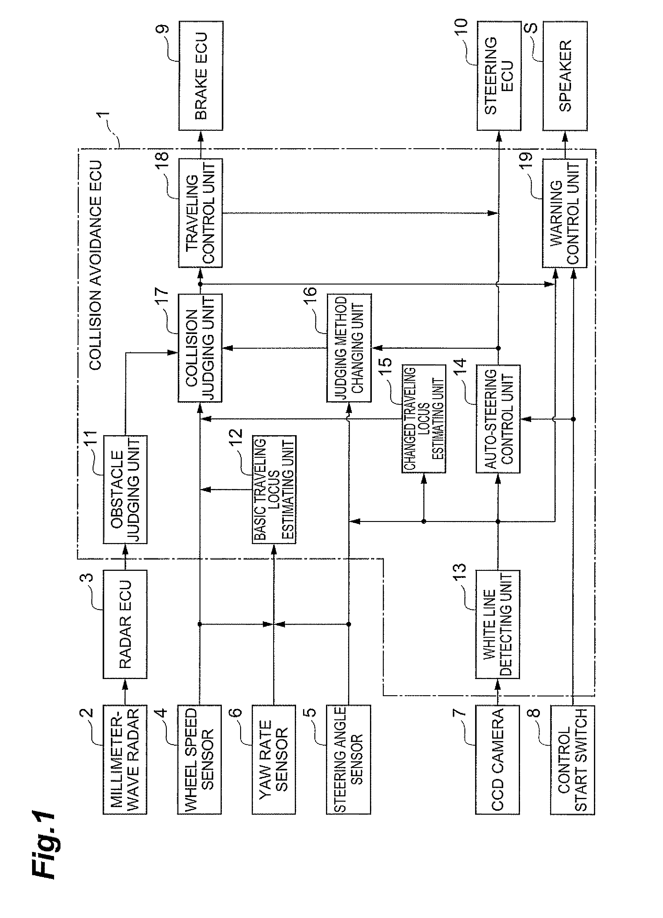
[0024]A first embodiment will be described. FIG. 1 is a block diagram showing a configuration of a collision avoidance device of the present embodiment. As shown in FIG. 1, the collision avoidance device of the present embodiment includes a collision avoidance ECU 1. To the collision avoidance ECU 1, a millimeter-wave radar 2 is connected via a radar ECU 3. Further, to the collision avoidance ECU 1, wheel speed sensors 4, a steering angle sensor 5, and a yaw rate sensor 6 are connected. To the collision avoidance ECU 1, a CCD camera 7 and a control start switch 8 are connected, and a brake ECU 9 and a steering ECU 10 are connected. The collision avoidance ECU 1 is connected to a speaker S.

[0025]The collision avoidance ECU 1, the radar ECU 3, the brake ECU 9, and the steering ECU 10 are computers of automotive devices to be electronically controlled, and include a CPU (Central Processing Unit), a ROM (Read Only Memory), a RAM (Random Access Memory), and an input / output interface, etc...

second embodiment

[0063]FIG. 5 is a flowchart showing steps of judging method changing determination in the collision avoidance device of the

[0064]As shown in FIG. 5, in the judging method changing determination in the collision avoidance device of the present embodiment, it is judged whether auto-steering control or departure warning control has been performed through the same steps as in the first embodiment (S21). As a result, when it is judged that auto-steering control or departure warning control has been performed, it is judged whether the driver has performed a course changing operation (S22). As a result, when it is judged that a course changing operation has not been operated by the driver, it is judged whether an own vehicle departs from an own lane (S23). The steps so far are the same as in the first embodiment.

[0065]As a result of the judgment of Step S23, when it is judged that an own vehicle does not depart from an own lane, it is judged whether the obstacle judged by the obstacle judg...

third embodiment

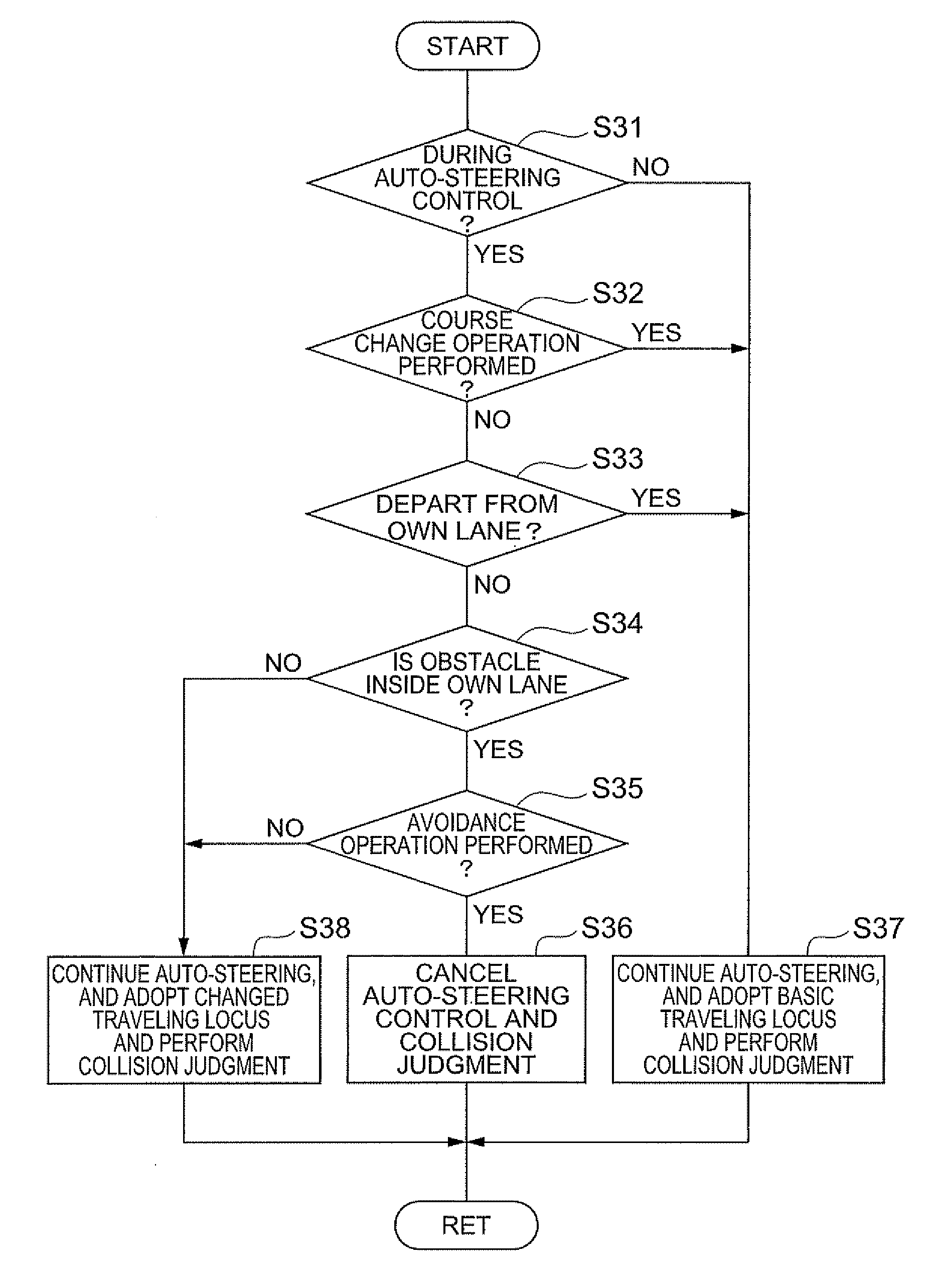
[0071]FIG. 7 is a flowchart showing steps of judging method changing determination in a collision avoidance device of a

[0072]As shown in FIG. 7, in the judging method changing steps in the collision avoidance device of the present embodiment, it is judged whether auto-steering control or departure warning control has been performed through the same steps as in the above-described first embodiment (S31). As a result, when it is judged that auto-steering control or departure warning control has been performed, it is judged whether the driver has performed a course changing operation (S32). As a result, when it is judged that the driver has not performed the course changing operation, it is judged whether an own vehicle departs from an own lane (S33). The steps so far are the same as in the above-described first embodiment.

[0073]As a result of the judgment of Step S33, when it is judged that an own vehicle does not depart from an own lane, it is judged whether an obstacle exists inside...


PUM


Abstract

A collision avoidance ECU estimates a traveling locus based on an estimated curve radius of an own vehicle in a basic traveling locus estimating unit, and in a changed traveling locus estimating unit, obtains separation distances between an own vehicle and white lines based on the relative positional relationship between an own vehicle and the white lines, and estimates, as a changed traveling locus, a route along the white lines with the obtained separation distances maintained. In a collision judging unit, when auto-steering control and departure warning control are not performed, collision judgment is performed based on the basic traveling locus estimated in the basic traveling locus estimating unit, and when the auto-steering control and departure warning control are performed, the traveling locus is changed to the changed traveling locus estimated in the changed traveling locus estimating unit and collision judgment is performed.

Description

TECHNICAL FIELD[0001]The present invention relates to a collision avoidance device which avoids a collision of an own vehicle with an obstacle such as another vehicle.BACKGROUND ART[0002]In a conventional vehicle, when there is a probability that an own vehicle will collide with an obstacle around the vehicle, to avoid a collision, a collision avoidance device which controls traveling and issues a warning to drivers has been provided. As such a collision avoidance device, there is a steering stability controller disclosed in Japanese Published Unexamined Patent Application No. 2001-114081. This steering stability controller includes a collision judging device which judges whether a vehicle will collide with an obstacle by detecting the obstacle around the vehicle and a lane departure judging device which judges whether the vehicle will depart from a lane in which the vehicle is currently traveling by detecting the lane. In this steering stability controller even during steering stab...

Claims


Application Information

Patent Timeline
Patent Type & Authority Applications(United States)
IPC IPC(8): B60W30/08G08G1/16B62D6/00B60R21/00B60T7/12B60T8/17B60W10/18B60W10/184B60W10/20B60W30/00B60W30/095B60W30/12B62D5/04B62D101/00B62D107/00B62D113/00B62D137/00
CPCB60T7/22B60T2201/022B60T2201/08B60T2201/087B62D5/0463B60W40/072B60W40/076B60W2420/52B62D15/0265B60W30/09G08G1/165G08G1/166B60W2420/408
Inventor OKITA, TOSHINORI
Owner TOYOTA JIDOSHA KK
Learn More