Distributed pico-cell mobility
a pico-cell and mobility technology, applied in the field of distributed pico-cell mobility, can solve the problem of restricted ieeee 802.11 system typical range, and achieve the effect of more efficient mobility
- Summary
- Abstract
- Description
- Claims
- Application Information
AI Technical Summary
Benefits of technology
Problems solved by technology
Method used
Image
Examples
first embodiment
of the Invention
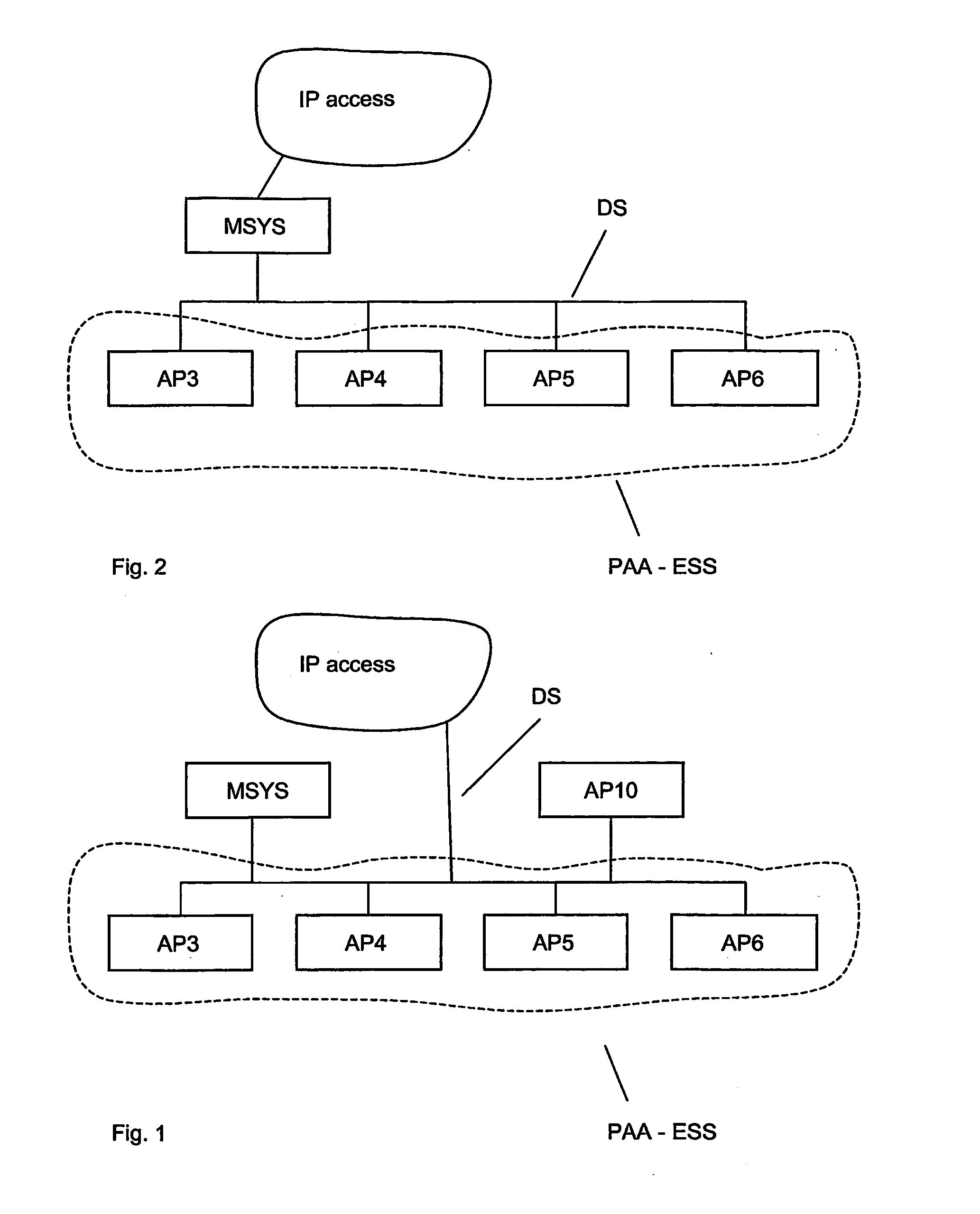
[0023]In FIG. 1, a first embodiment of a network has been shown. The network comprises a number of access points AP3, AP4, AP5 . . . AP6 connected with one another over a distribution system, DS, which provides Internet access. The above access points form a pre-authentication area, PAA, according to the invention and the access points may advantageously define a partly overlapping contiguous coverage, which may be arranged so as to follow a road or railway. Access points, AP10, which are not part of the PAA area may also be provided and connected to the distribution system. A system node, MSYS, may also be provided according to the invention, for authentication purposes.
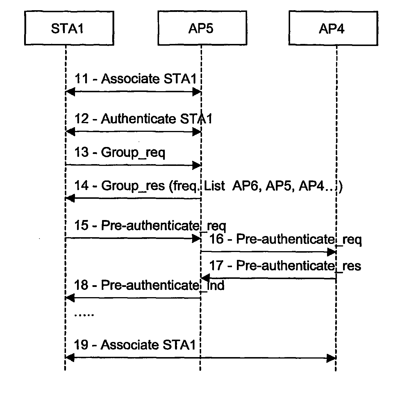
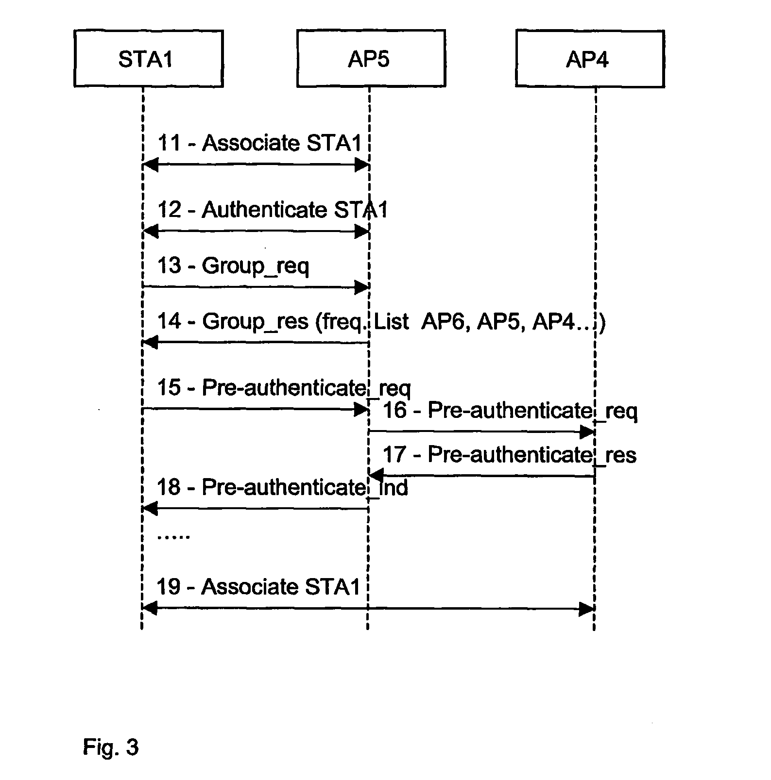
[0024]According to the first embodiment of the invention, the pre-authentication area, PAA, comprises a set of non-hierarchical access points as shown in FIG. 1 but without the MSYS node. Each access point constitutes the gateway towards the Internet. The access points are moreover connected with one...
second embodiment
of the Invention
[0031]In the second embodiment of the invention, the PA structure is hierarchical in the sense that a system node, MSYS, coupling the BSS constituted by the AP's in a pre-authentication area, provides access to the Internet. In FIG. 2, a second embodiment of the network according to the invention is provided. The network differs from the network shown in FIG. 1, in that the system node is a gateway to the Internet access network. FIG. 4 shows a timing diagram pertaining to the second embodiment of the invention.
[0032]In this embodiment the MSYS has the role of performing the exclusive authentication of stations entering the pre-authentication area or providing additional authentication of stations. If the authentication is approved for a given station, access is given to that station.
[0033]In step 21, respectively step 22, the legacy step of association towards a first encountered access point—in this case AP5—is accomplished. Step 22—the station authenticating itsel...
third embodiment
of the Invention
[0039]This embodiment, like the above embodiment, comprises a gateway node controlling access to the Internet, as shown in FIG. 2. FIG. 5 shows a timing diagram of the third embodiment of the invention.
[0040]In this embodiment, there is no authentication before the access points of the pre-authentication area, PAA.
[0041]After the association in step 32, the station authenticates, step 33, with the gateway node, MSYS. Messages are communicated over the distribution system between the associated access point and the gateway node.
[0042]The station then issues a group request message, 34, signalling to the gateway node that is interested in being pre-authenticated for other access point's in the pre-authentication area, PAA. The station may refrain from issuing the request if this is determined by upper layer programs, for instance as a result of the station being stationary or moving in an local area including other access point's, which are not part of the pre-authenti...
PUM
 Abstract
Description
Claims
Application Information
 - R&D
- Intellectual Property
- Life Sciences
- Materials
- Tech Scout
- Unparalleled Data Quality
- Higher Quality Content
- 60% Fewer Hallucinations
Browse by: Latest US Patents, China's latest patents, Technical Efficacy Thesaurus, Application Domain, Technology Topic, Popular Technical Reports.
© 2025 PatSnap. All rights reserved.Legal|Privacy policy|Modern Slavery Act Transparency Statement|Sitemap|About US| Contact US: help@patsnap.com


