Intelligent shrimp culture pond control system based on Internet of Things and control method thereof
A technology of control system and control method, applied in fish farming, application, climate change adaptation, etc., can solve problems such as heavy workload, low work efficiency, uneven feeding, etc., to improve efficiency, improve practicability, and save The effect of manpower and material resources
- Summary
- Abstract
- Description
- Claims
- Application Information
AI Technical Summary
Problems solved by technology
Method used
Image
Examples
Embodiment 1
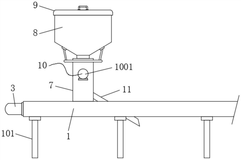
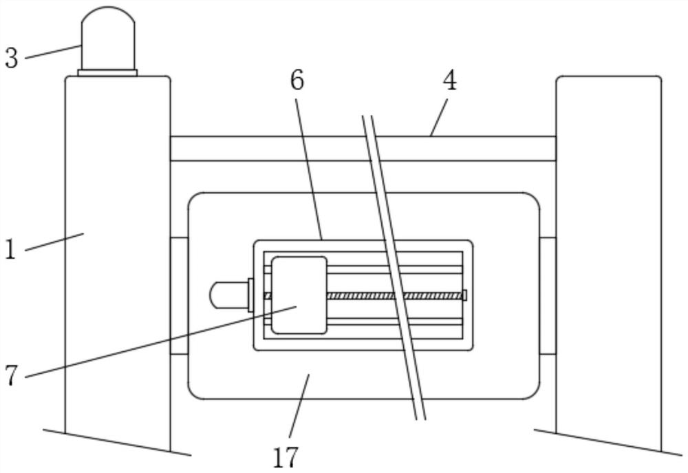
[0035] Embodiment one, by Figure 1 to Figure 6 Given, the present invention includes two horizontal plates 1 and a control system 2, and the bottoms of the two horizontal plates 1 are fixedly equipped with stabilizing support rods 101 at equal distances. Installed on both sides of the shrimp pond, one end of one of the horizontal plates 1 is installed with the first forward and reverse motor 3, and a transmission link 4 is installed between the opposite sides of the two horizontal plates 1, and the two horizontal plates 1 The interior is equipped with a lateral movement mechanism 5, and the two ends of the transmission link 4 are connected to the two transverse movement mechanisms 5 respectively. Through the setting of the transmission link 4, the two transverse movement mechanisms 5 can be effectively rotated and adjusted. A fixed plate 17 is installed between the two lateral movement mechanisms 5, and a horizontal adjustment mechanism 6 is installed on the top of the fixed ...
Embodiment 2
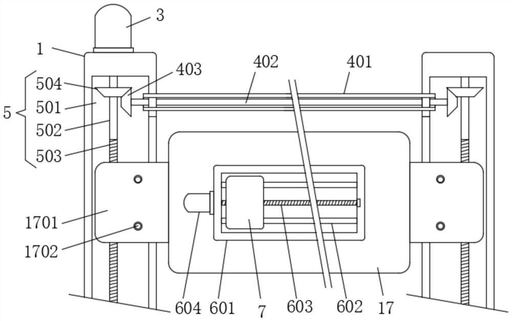
[0036] Embodiment two, on the basis of embodiment one, by image 3 Given, the two lateral moving mechanisms 5 all include a moving slot 501, a driving shaft 502, a threaded end 503 and a first bevel gear 504, the moving slot 501 is set on one side of the horizontal plate 1, and the driving shaft 502 is rotated and installed Inside the moving slot 501, the threaded end 503 is set on the surface of the driving shaft 502, the first bevel gear 504 is fixedly installed on one end of the driving shaft 502, and the output end of the first forward and reverse motor 3 is connected to one of the moving slots 501. One end of the fixed phase connection, so that the lateral movement can be effectively adjusted.
Embodiment 3
[0037] Embodiment three, on the basis of embodiment one, by image 3 Given, the transmission connecting rod 4 includes a connecting pipe 401, a transmission rotating shaft 402 and two second bevel gears 403, the connecting pipe 401 is fixedly installed between the opposite ends of the two horizontal plates 1, and the transmission rotating shaft 402 is rotatably installed on the connecting pipe Inside the 401, two second bevel gears 403 are fixedly installed on both ends of the transmission shaft 402 respectively, the connecting pipe 401 communicates with the two moving slots 501, and the two second bevel gears 403 are connected with the two first bevel gears respectively. 504 are engaged, so that the two lateral movement mechanisms 5 can rotate synchronously.
PUM
 Abstract
Description
Claims
Application Information
 - R&D
- Intellectual Property
- Life Sciences
- Materials
- Tech Scout
- Unparalleled Data Quality
- Higher Quality Content
- 60% Fewer Hallucinations
Browse by: Latest US Patents, China's latest patents, Technical Efficacy Thesaurus, Application Domain, Technology Topic, Popular Technical Reports.
© 2025 PatSnap. All rights reserved.Legal|Privacy policy|Modern Slavery Act Transparency Statement|Sitemap|About US| Contact US: help@patsnap.com


