Pressure Relief Device for a Gear Box

Inactive Publication Date: 2010-02-11
LIN CHUNG CHUAN
View PDF5 Cites 12 Cited by
  • Summary
  • Abstract
  • Description
  • Claims
  • Application Information

AI Technical Summary

Benefits of technology

[0008]The primary objective of the present invention is to provide a pressure relief device for a gear box which utilizes a spring to push a blocking member and make it seal a penetrating hole, when gas pressure in the gear box is enough to compress the spring, the gas will be d

Problems solved by technology

When the gear box is an enclosed space, the pressure inside the gear box will continuously rise, and when the structural intensity of th

Method used


Image

  • Pressure Relief Device for a Gear Box
  • Pressure Relief Device for a Gear Box
  • Pressure Relief Device for a Gear Box

Examples


Embodiment Construction

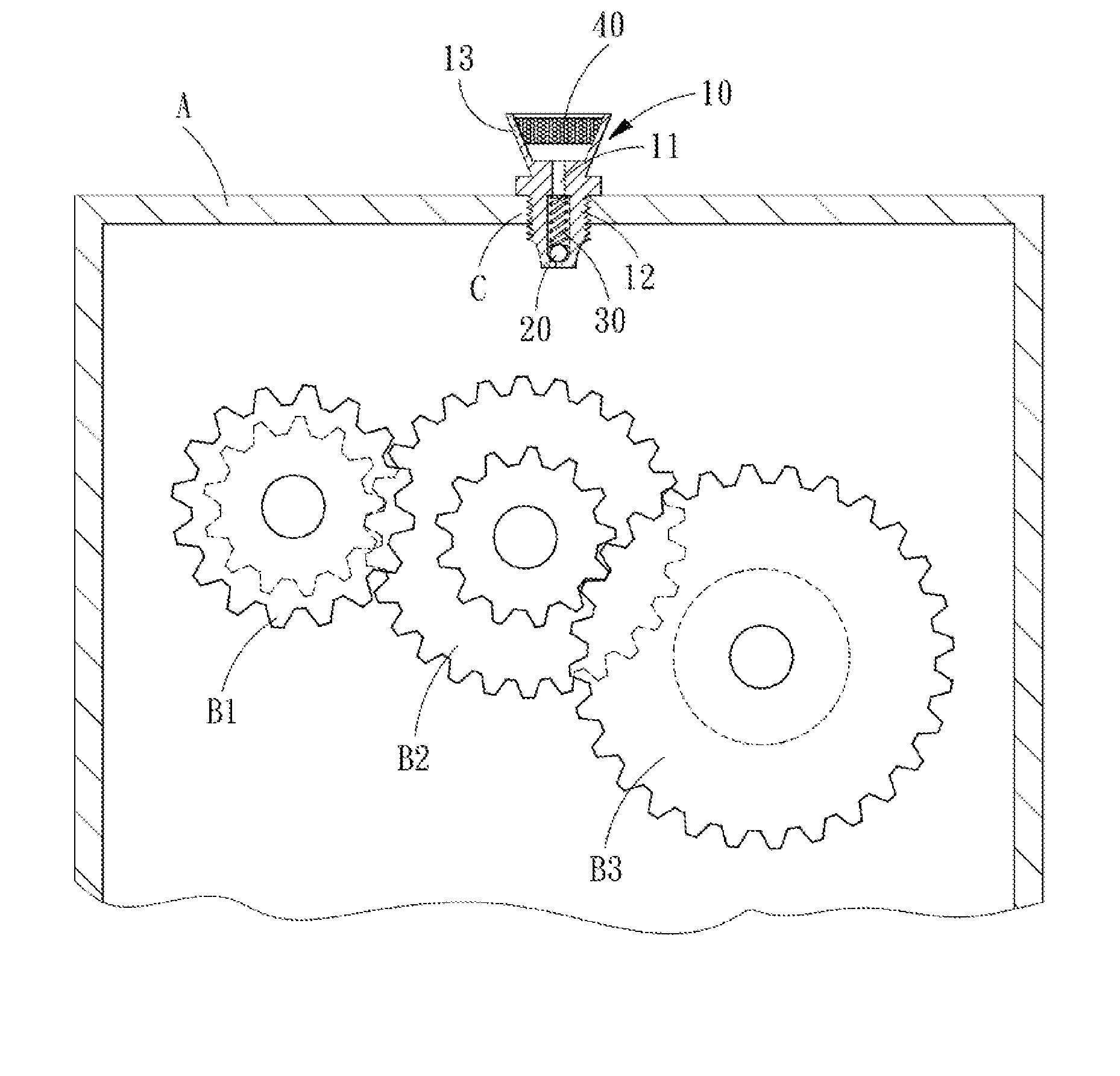
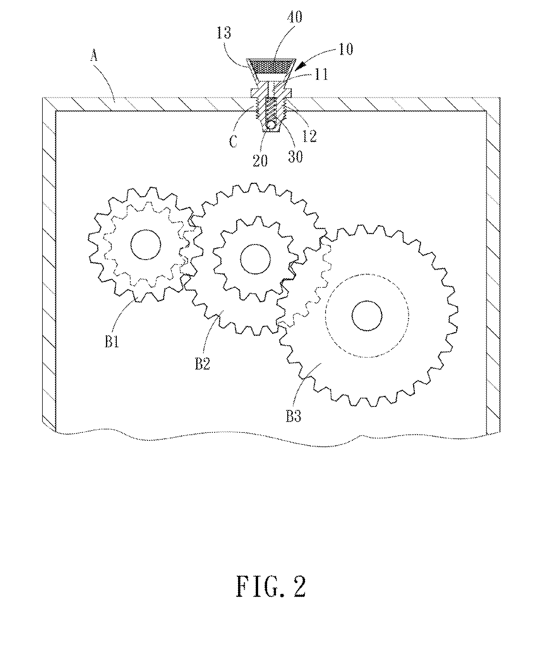
[0016]Referring to FIGS. 2 and 3, a pressure relief device for a gear box in accordance with the present invention is disposed in a through hole C of a housing A and comprises a body 10, a blocking member 20, an elastic member 30 and a sponge 40.

[0017]The body 10 is defined with a penetrating hole 11 and is pipe-shaped. One end of the body 10 is defined with outer threads 12, and the through hole C of the housing A is defined with inner threads to be threaded with the outer threads 12 of the body 10. The penetrating hole 11 of the body 10 enables an inner part to communicate with an outer part of the housing A. The penetrating hole 11 comprises three orderly connected portions, that is, an inlet portion 111, a ventilating portion 112 and an outlet portion 113. The inlet portion 111 is in communication with the inner part of the housing A, and the outlet portion 113 is in communication with the outer part of the housing A. The caliber of the inlet portion 111 is smaller than that of ...


PUM


Abstract

A pressure relief device for a gear box which is disposed in the gear box and comprises a body, a blocking member and a spring. The body is defined with a penetrating hole. The spring pushes the blocking member and makes it seal the penetrating hole. When the pressure rises since the temperature therein is risen, and when the gas pressure in the gear box is larger than the force of the spring, the gas can push the blocking member and compress the spring, and then discharge from the penetrating hole of the body, thus reducing the pressure and the temperature of the gear box.

Description

BACKGROUND OF THE INVENTION[0001]1. Field of the Invention[0002]The present invention relates to a component for a transmission device, and more particularly to a pressure relief device for a gear box.[0003]2. Description of the Prior Art[0004]A conventional gear box usually comprises a housing in which a plurality of gears being engaged with each other are disposed, and such a gear box can be used as a vehicle transmission box, or a speed changing device for a rotary cutting mechanism. In order to make the gears perform rotation and engaging movement more smoothly, the lubricating oil, such as machine oil or gear oil, is provided on the gears. However, when performing high speed, or long time rotation and engaging movement, the gears will produce heat energy and oil gas due to friction, such that the gas temperature in the gear box will be risen and the gas will be expanded. When the gear box is an enclosed space, the pressure inside the gear box will continuously rise, and when th...

Claims


Application Information

Patent Timeline
IPC IPC(8): F01M1/16
CPCF01M13/00F16K17/0406F16H57/027F01M2013/0438
Inventor LIN, CHUNG-CHUAN
Owner LIN CHUNG CHUAN
Why Eureka
Try Eureka