Eureka AIR delivers breakthrough ideas for toughest innovation challenges, trusted by R&D personnel around the world.

Turbine generator having direct magnetic gear drive

a technology of magnetic gear drive and turbine generator, which is applied in the direction of electric generator control, renewable energy generation, greenhouse gas reduction, etc., can solve the problems of mechanical gear system power loss and substantial maintenan

Inactive Publication Date: 2010-02-11
DEXTER MAGNETIC TECH
View PDF5 Cites 14 Cited by
  • Summary
  • Abstract
  • Description
  • Claims
  • Application Information

AI Technical Summary

Benefits of technology

[0009]A turbine operated electric generator according to one aspect of the invention includes a turbine and a magnetic gear unit rotationally coupled at an input thereof to a turbine. An output of the magnetic gear unit is configured to operate an electric generator. The magnetic gear unit includes magnets configured to at least one of increase a rotation speed at the output with respect to the input speed and inversely change a torque at the output with respect to the input and decrease the output speed with respect to the input speed and inversely change the torque.

Problems solved by technology

Typically, such turbines are coupled to the electric generator using a gear system to increase the rotation speed of the generator because the rotation speed of the turbine is typically not sufficient to operate the generator.
Mechanical gear systems are subject to power loss due to friction and require substantial maintenance.

Method used


Image

  • Turbine generator having direct magnetic gear drive
  • Turbine generator having direct magnetic gear drive
  • Turbine generator having direct magnetic gear drive

Examples


Embodiment Construction

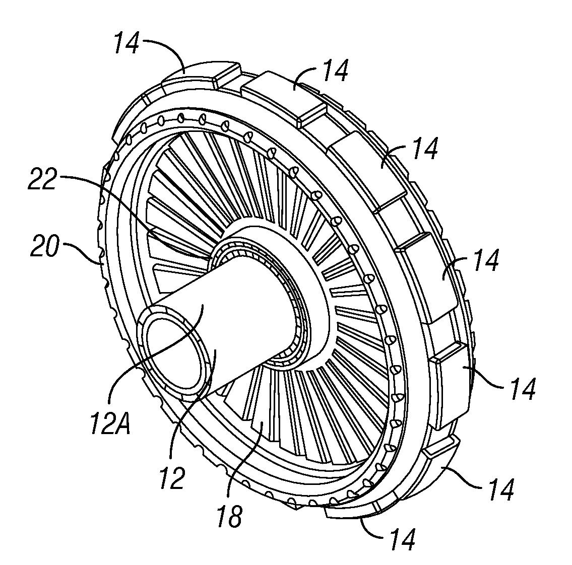
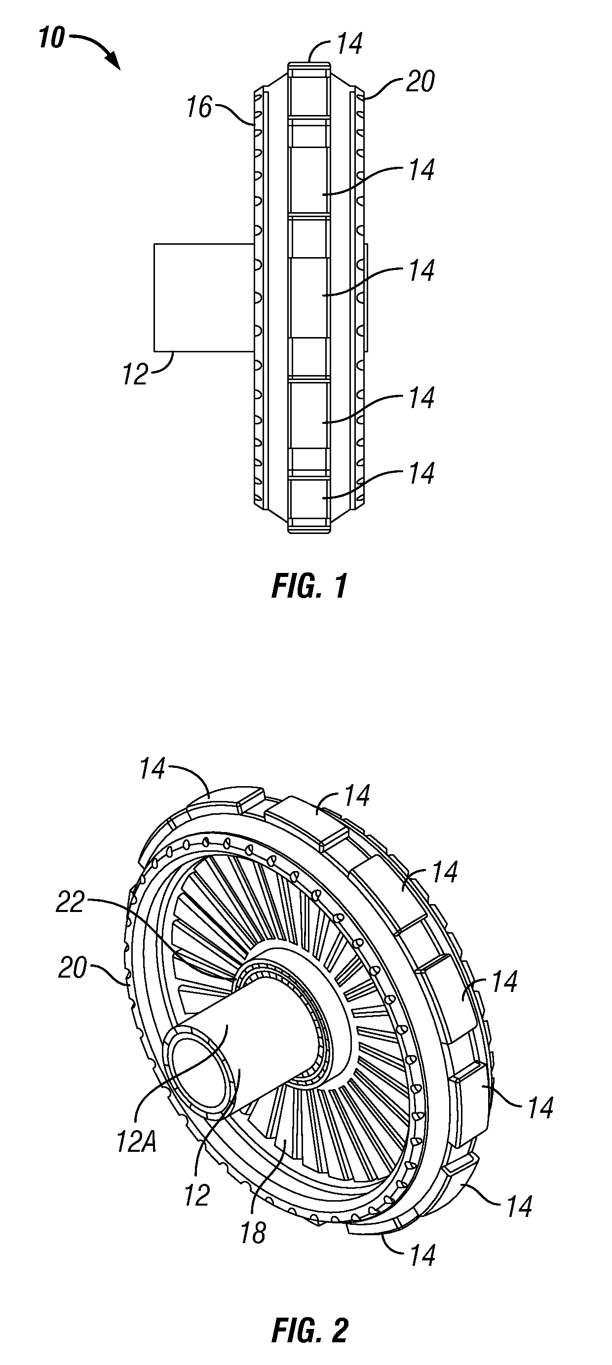
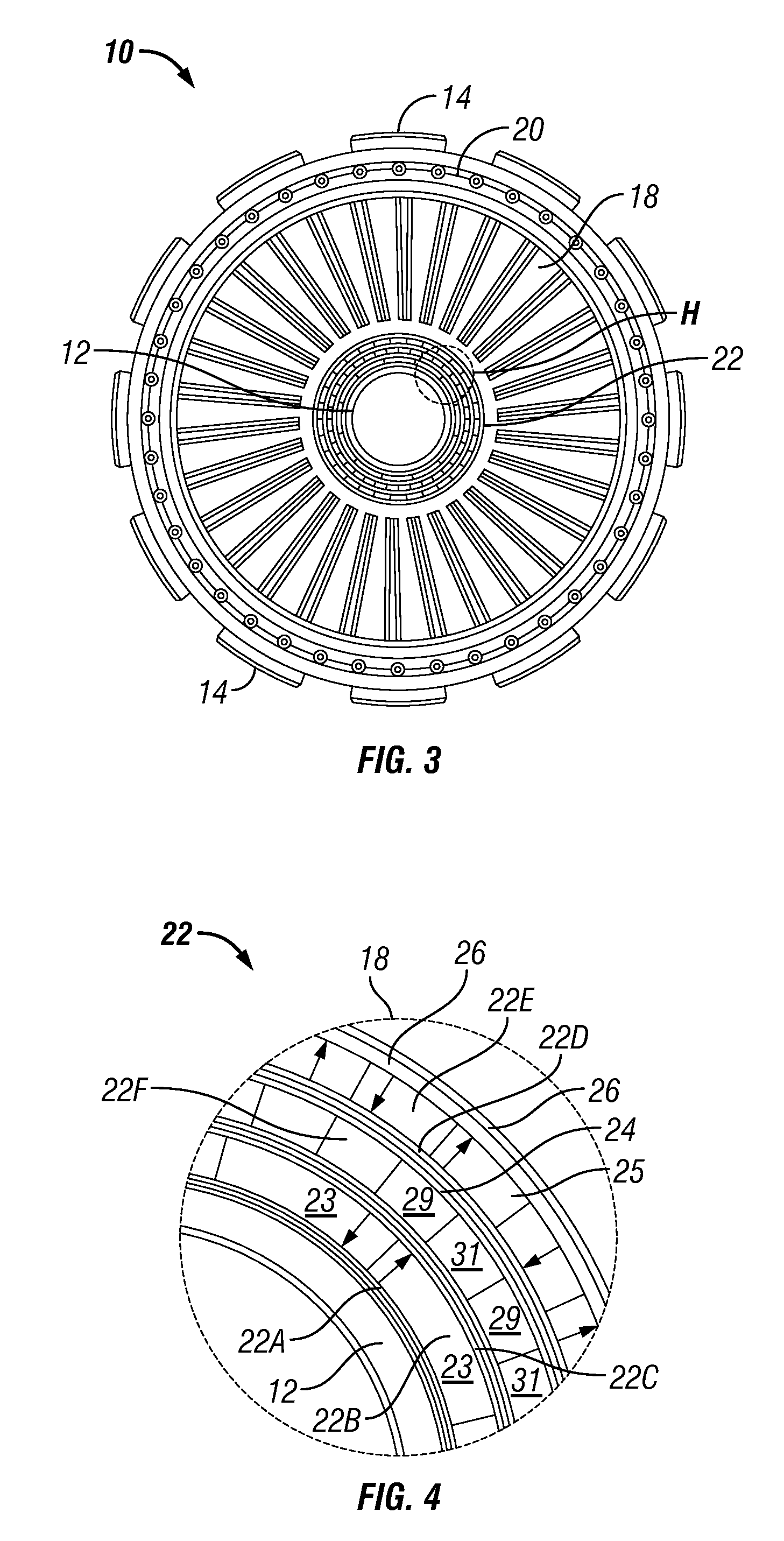
[0019]FIG. 1 is a side view of an example direct drive, magnetically geared electric generator. The present example generator 10 includes an inner stator 12, which may include a plurality of wire coils (FIG. 4) arranged to convert movement of magnets (explained below) proximate thereto into electric power. An inner magnetic gear unit (22 in FIG. 2) is rotationally coupled at its input to an inner edge of a turbine (18 in FIG. 2) and its output is rotationally coupled to the magnets that excite the wire coils in the inner stator. One arrangement of magnets will be further explained below with reference to FIG. 4. Electrical connections to the coils can be conventional and are omitted from the drawings for clarity.

[0020]An outer magnetic gear unit 20 may be rotationally coupled at its input to the outer edge of the turbine (18 in FIG. 2). The outer magnetic gear unit 20 couples rotation of the turbine (18FIG. 2) to magnets (45 in FIG. 6) disposed rotationally proximate an outer stator...


PUM


Abstract

A turbine operated electric generator includes a turbine and a magnetic gear unit rotationally coupled at an input thereof to at least one of an inner rim of the turbine and an outer rim of the turbine. An output of the magnetic gear unit is configured to operate an electric generator. The magnetic gear unit includes magnets configured to at least one of increase a rotation speed at the output with respect to the input speed and inversely change a torque at the output with respect to the input and decrease the output speed with respect to the input speed and inversely change the torque.

Description

CROSS-REFERENCE TO RELATED APPLICATIONS[0001]Priority is claimed from U.S. Provisional Application No. 61 / 087,183 filed on Aug. 8, 2008.STATEMENT REGARDING FEDERALLY SPONSORED RESEARCH OR DEVELOPMENT[0002]Not applicable.BACKGROUND OF THE INVENTION[0003]1. Field of the Invention[0004]The invention relates generally to the field of electric power generation. More specifically, the invention relates to devices for driving electric generators using wind or water as the prime mover.[0005]2. Background Art[0006]Wind or water operated turbines are known in the art for driving electric generators. Typically, such turbines are coupled to the electric generator using a gear system to increase the rotation speed of the generator because the rotation speed of the turbine is typically not sufficient to operate the generator.[0007]Gear systems known in the art for use with turbine powered generators are typically mechanically implemented. Mechanical gear systems are subject to power loss due to f...

Claims


Application Information

Patent Timeline
Patent Type & Authority Applications(United States)
IPC IPC(8): F03B13/00H02K7/10
CPCF01D1/20F03B3/126F05B2220/7066F05D2220/766Y02E10/223H02K7/1823H02K49/102Y02E10/20
Inventor HATCH, GARETH P.PLAMP, BENJAMIN C.
Owner DEXTER MAGNETIC TECH
Why Eureka
Eureka Blog
Learn More