LED drive circuit

Inactive Publication Date: 2010-02-11
SHARP KK
View PDF3 Cites 30 Cited by
  • Summary
  • Abstract
  • Description
  • Claims
  • Application Information

AI Technical Summary

Benefits of technology

[0026]Moreover, the over-temperature protection portion may limit the output of the

Problems solved by technology

Thus, with the conventional LED drive circuit shown in FIG. 20, a rise in temperature possibly leads to a current falling beyond a predetermined value injected into the LEDs.
Thus, there is a possibility that the LED module 3 or the LED drive circuit is broken at worst if its ambient temperature rises abnormally high, or if a short circuit occurs between an anode terminal and a cathode terminal of the LED module 3.
Moreover, if an excessive load is imposed, an incande

Method used


Image

  • LED drive circuit
  • LED drive circuit
  • LED drive circuit

Examples


first embodiment

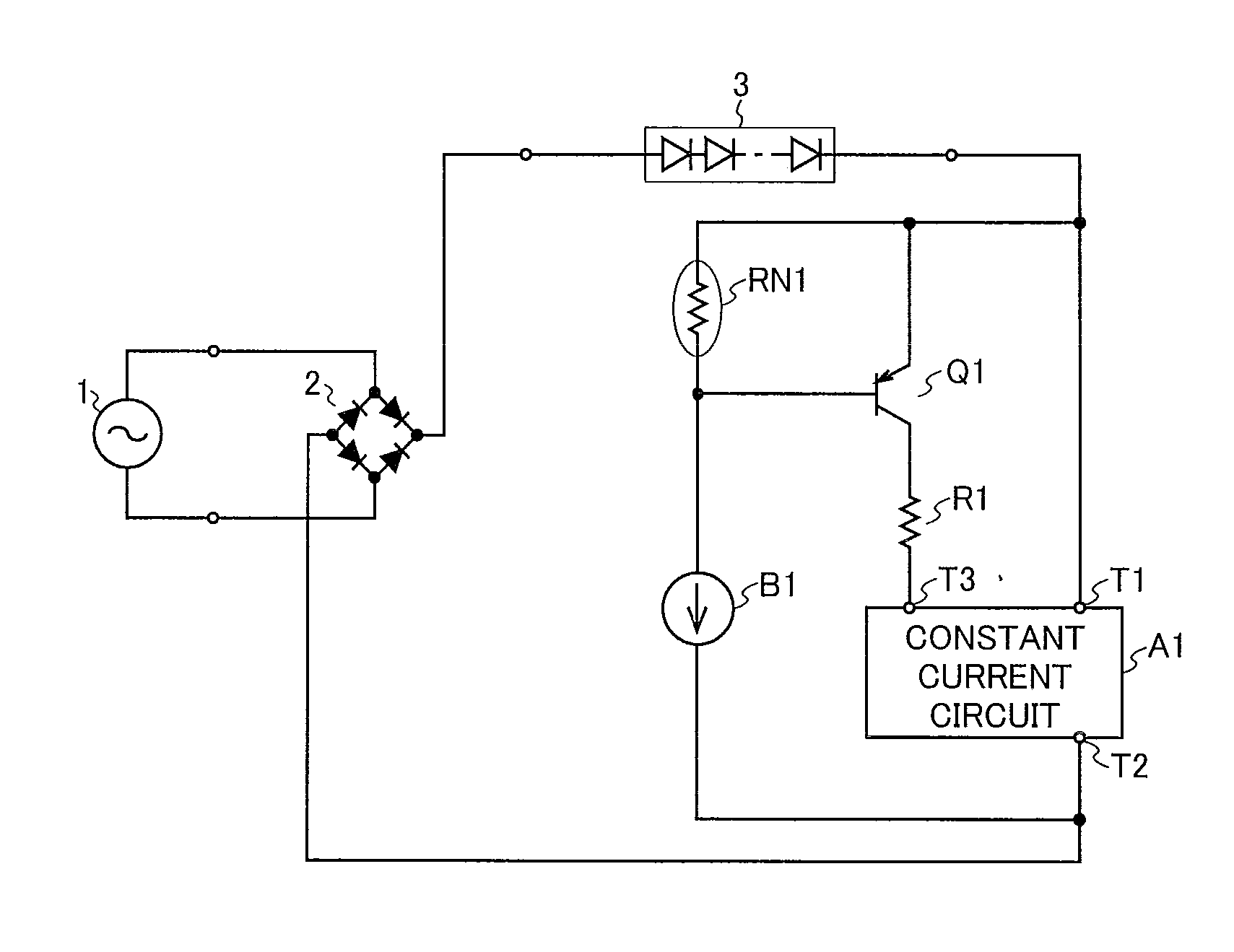
[0052]A configuration of an LED drive circuit according to a first embodiment of the present invention is shown in FIG. 1. The LED drive circuit of this embodiment shown in FIG. 1 is provided with: a bridge diode 2; constant current circuits A1 and B1; a PNP transistor Q1; a resistor R1; and a negative temperature coefficient resistor RN1 such as an NTC thermistor (hereinafter, referred to as “NTC resistor RN1”).

[0053]The bridge diode 2 is, at an input end thereof, connected to a commercially available AC 100 V power source 1 and is, at one output end thereof, connected to an anode of the LED module 3. The constant current circuit A1 is, at a constant current terminal T1 thereof, connected to a cathode of the LED module 3 and is, at a constant current terminal T2 thereof, connected to the other output end of the bridge diode 2. The PNP transistor Q1 is, at an emitter thereof, connected to a cathode of the LED module 3 and is, at a collector thereof, connected to a bias current termi...

second embodiment

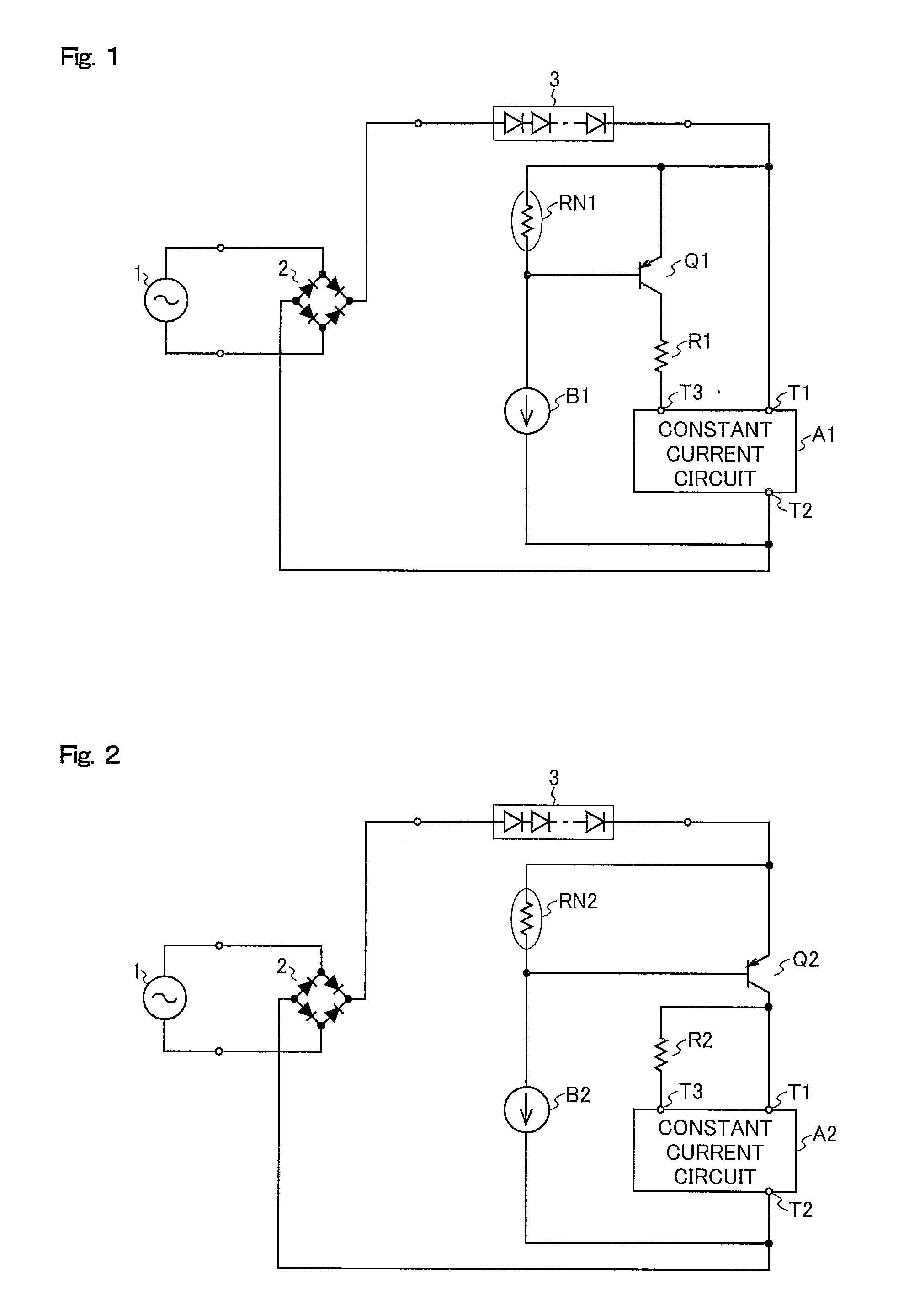
[0059]A configuration of an LED drive circuit according to a second embodiment of the present invention is shown in FIG. 2. The LED drive circuit of this embodiment shown in FIG. 2 is provided with: a bridge diode 2; constant current circuits A2 and B2; a PNP transistor Q2; a resistor R2; and a negative temperature coefficient resistor (hereinafter, referred to as “NTC resistor”) RN2.

[0060]The bridge diode 2 is, at an input end thereof, connected to the commercially available AC 100 V power source 1 and is, at one output end thereof, connected to the anode of the LED module 3. The cathode of the LED module 3 is connected to an emitter of the PNP transistor Q2. The constant current circuit A2 is, at a constant current terminal T1 thereof, connected to a collector of the PNP transistor Q2 and is, at a constant current terminal T2 thereof, connected to the other output end of the bridge diode 2. Moreover, the collector of the PNP transistor Q2 is connected to a bias current terminal T3...

third embodiment

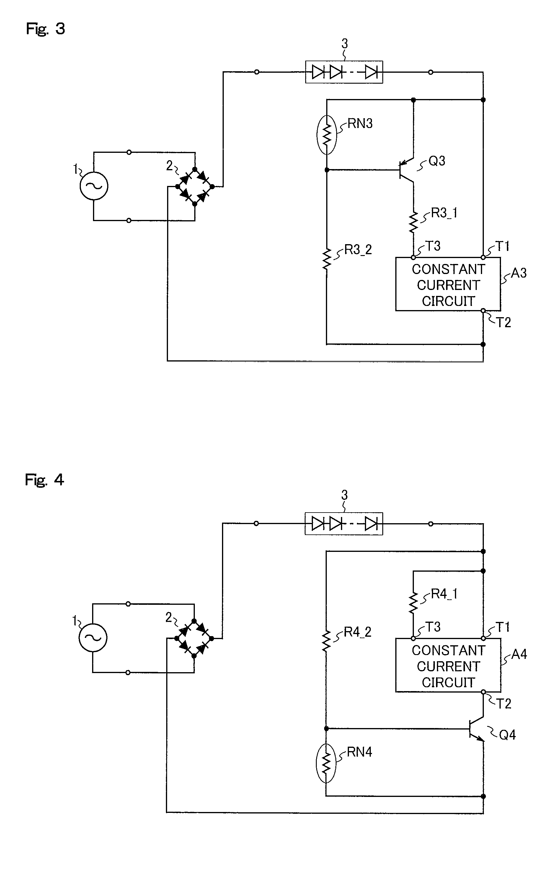
[0065]A configuration of an LED drive circuit according to a third embodiment of the present invention is shown in FIG. 3. The LED drive circuit of this embodiment shown in FIG. 3 is provided with: a bridge diode 2; a constant current circuit A3; a PNP transistor Q3; resistors R3_1 and R3_2; a negative temperature coefficient resistor (hereinafter, referred to as “NTC resistor”) RN3.

[0066]The bridge diode 2 is, at an input end thereof, connected to the commercially available AC 100 V power source 1 and is, at one output end thereof, connected to the anode of the LED module 3. The constant current circuit A3 is, at a constant current terminal T1 thereof, connected to the cathode of the LED module 3 and is, at a constant current terminal T2 thereof, connected to the other output end of the bridge diode 2. Moreover, the PNP transistor Q3 is, at an emitter thereof, connected to the cathode of the LED module 3 and is, at a collector thereof, connected to a bias current terminal T3 of the...


PUM


Abstract

An LED drive circuit that drives an LED is provided with: a rectifying circuit that converts an alternating voltage into a pulsating current; a constant current circuit; and an over-temperature protection portion that limits an output of the constant current circuit, wherein the LED and the constant current circuit are connected in series on an output side of the rectifying circuit.

Description

[0001]This nonprovisional application claims priority under 35 U.S.C. §119(a) on Patent Application No. 2008-202842 filed in Japan on Aug. 6, 2008 and Patent Application No. 2008-226788 filed in Japan on Sep. 4, 2008, the entire contents of which are hereby incorporated by reference.BACKGROUND OF THE INVENTION[0002]1. Field of the Invention[0003]The present invention relates to an LED drive circuit that drives an LED (light emitting diode).[0004]2. Description of the Related Art[0005]Featuring low power consumption and a long life, etc., the LED finds applications in increasingly wide areas, not only display apparatuses but also lighting equipment, etc. In the lighting equipment, a plurality of LEDs are used to obtain desired illumination.[0006]The LED shortens its life if receiving a current exceeding a rated current value. Therefore, the LED needs to be driven with a constant current or provided with current limitation so that no current above a predetermined level is passed there...

Claims


Application Information

Patent Timeline
IPC IPC(8): H05B37/02
CPCH05B33/0812Y02B20/341H05B33/089H05B45/395Y02B20/30H05B45/56
Inventor MARUYAMA, YASUHIROSHOJI, HIROYUKI
Owner SHARP KK
Why Eureka
Try Eureka