Converting Mechanical Vibrational Energy Into Electrical Energy

Active Publication Date: 2010-02-11
HITACHI RAIL LTD +1
View PDF15 Cites 17 Cited by
  • Summary
  • Abstract
  • Description
  • Claims
  • Application Information

AI Technical Summary

Benefits of technology

[0011]The present invention aims to provide an improved electromechanical generator for converting mechanical v

Problems solved by technology

While this prior disclosure produced a useful mechanism for designing a theoretical electromechanical generator, when an electromechanical generator is used in a practical application, it is not possible accurately to predict the resonant frequency or the optimal damping factor.
However, there is no guarantee that the practical operating conditions correspond to the theoretical ideal used to set up the electromechanical generator for the specific application.
However, it

Method used


Image

  • Converting Mechanical Vibrational Energy Into Electrical Energy
  • Converting Mechanical Vibrational Energy Into Electrical Energy
  • Converting Mechanical Vibrational Energy Into Electrical Energy

Examples


Example

COMPARATIVE EXAMPLE 1

[0089]An energy harvesting device not in accordance with the present invention is constructed with a fixed damping coefficient of c=0.005 Nsm−1, referring to FIG. 2, so as to be able to produce a maximum peak output power. However, the vibration frequency range for achieving the maximum peak output power is very narrow. If the vibration frequency changes over time, or is different in practice from the intended value upon which the design was based, then the output power is significantly reduced, and may even not be a useful output power.

Example

COMPARATIVE EXAMPLE 2

[0090]An energy harvesting device not in accordance with the present invention is constructed with a fixed damping coefficient of c=0.005 Nsm−1, referring to FIG. 2, so as to be able to produce a maximum peak output power and connected to control circuitry. The circuitry is designed in such a way that if the device produces more than 10 mW of electrical power then it can tune the resonant frequency of the device by means of an actuator. In this way the resonance can be aligned with the vibration source and high power output can be achieved. FIG. 2 shows that (ignoring all parasitic losses for sake of clarity) the circuitry will start up if the vibration frequency is between 46.8 Hz and 54.8 Hz. However, if the vibration starts outside of this range, say at 70 Hz, then the device will not operate (making the reasonable assumption that the device has no energy store).

Example

EXAMPLE 1

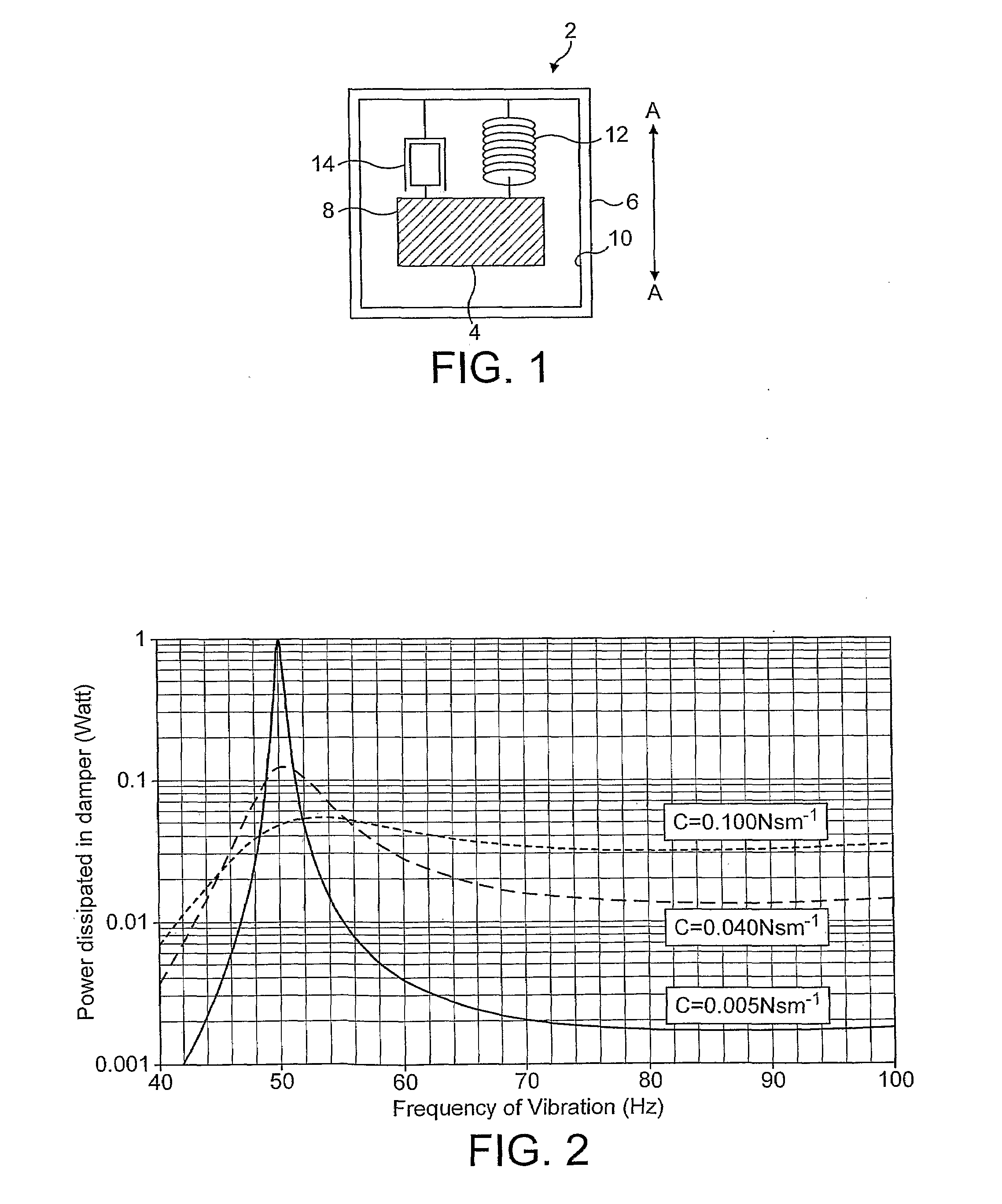
[0091]An energy harvesting device in accordance with the present invention is constructed with a variable damping coefficient and connected to control circuitry. The circuitry is designed in such a way that if the device produces more than 10 mW of electrical power then it can tune the resonant frequency of the device by means of an actuator and can tune the damping coefficient. Initially, the damping coefficient is set at c=0.1 Nsm−1, permitting an allowable start-up frequency range of from 41.6 Hz and extending to much higher frequencies for producing the required 10 mW output. Nevertheless, once tuned the device would produce relatively low output power. Therefore the damping coefficient can be reduced to c=0.005 Nsm−1 so as to be able to produce a maximum peak output power with the resonance aligned with the vibration source. Therefore, it is clear that optimum power output can reliably be achieved by utilizing the ability to tune both resonant frequency and damping co...


PUM


Abstract

An electromechanical generator comprising an electromechanical device for converting mechanical vibrational energy into electrical energy, the electromechanical device being a velocity damped resonator having a damping coefficient and a resonant frequency, a power detector for detecting the output electrical power from the electromechanical device, a controller, and a damping coefficient adjuster for adjusting the damping coefficient of the electromechanical device, the controller being arranged to control the damping coefficient adjuster in response to the output electrical power detected by the power detector.

Description

FIELD OF THE INVENTION[0001]The present invention relates to an electromechanical generator for converting mechanical vibrational energy into electrical energy and to a method of converting mechanical vibrational energy into electrical energy. In particular, the present invention relates to such a device which is a miniature generator capable of converting ambient vibration energy into electrical energy for use, for example, in powering intelligent sensor systems. Such a system can be used in inaccessible areas where wires cannot be practically attached to provide power or transmit sensor data.BACKGROUND OF THE INVENTION[0002]There is currently an increasing level of research activity in the area of alternative power sources for micro electrical mechanical systems (MEMS) devices, such devices being described in the art as being used for ‘energy harvesting’ and as ‘parasitic power sources’. Such power sources are currently being investigated for powering wireless sensors.[0003]It is ...

Claims


Application Information

Patent Timeline
IPC IPC(8): H02P9/04H02N2/18F03G7/08H02K35/00H02P25/02
CPCH02K35/00H02P9/04H02P2101/30H04W52/0258H02P25/027H02P25/032Y02D30/70G05D19/02
Inventor ROBERTS, STEPHENFREELAND, ROY
Owner HITACHI RAIL LTD
Why Eureka
Try Eureka