Display apparatus, driving apparatus of display apparatus, and electronic device

Inactive Publication Date: 2010-02-11
SHARP KK
View PDF24 Cites 20 Cited by
  • Summary
  • Abstract
  • Description
  • Claims
  • Application Information

AI Technical Summary

Benefits of technology

[0047]This makes it possible to provide an electronic device

Problems solved by technology

In a case where a slit of the first liquid crystal panel and a slit of the second liquid crystal panel overlap each other, interference fringes are caused.
This causes a problem of deterioration in display quality of a liquid cr

Method used


Image

  • Display apparatus, driving apparatus of display apparatus, and electronic device
  • Display apparatus, driving apparatus of display apparatus, and electronic device
  • Display apparatus, driving apparatus of display apparatus, and electronic device

Examples


Embodiment Construction

[0073]The following describes an embodiment of the present invention.

[0074]The present embodiment deals with a liquid crystal display apparatus in which two transmissive liquid crystal panels are combined with each other, each of the transmissive liquid crystal display panels being used as a transmissive display panel.

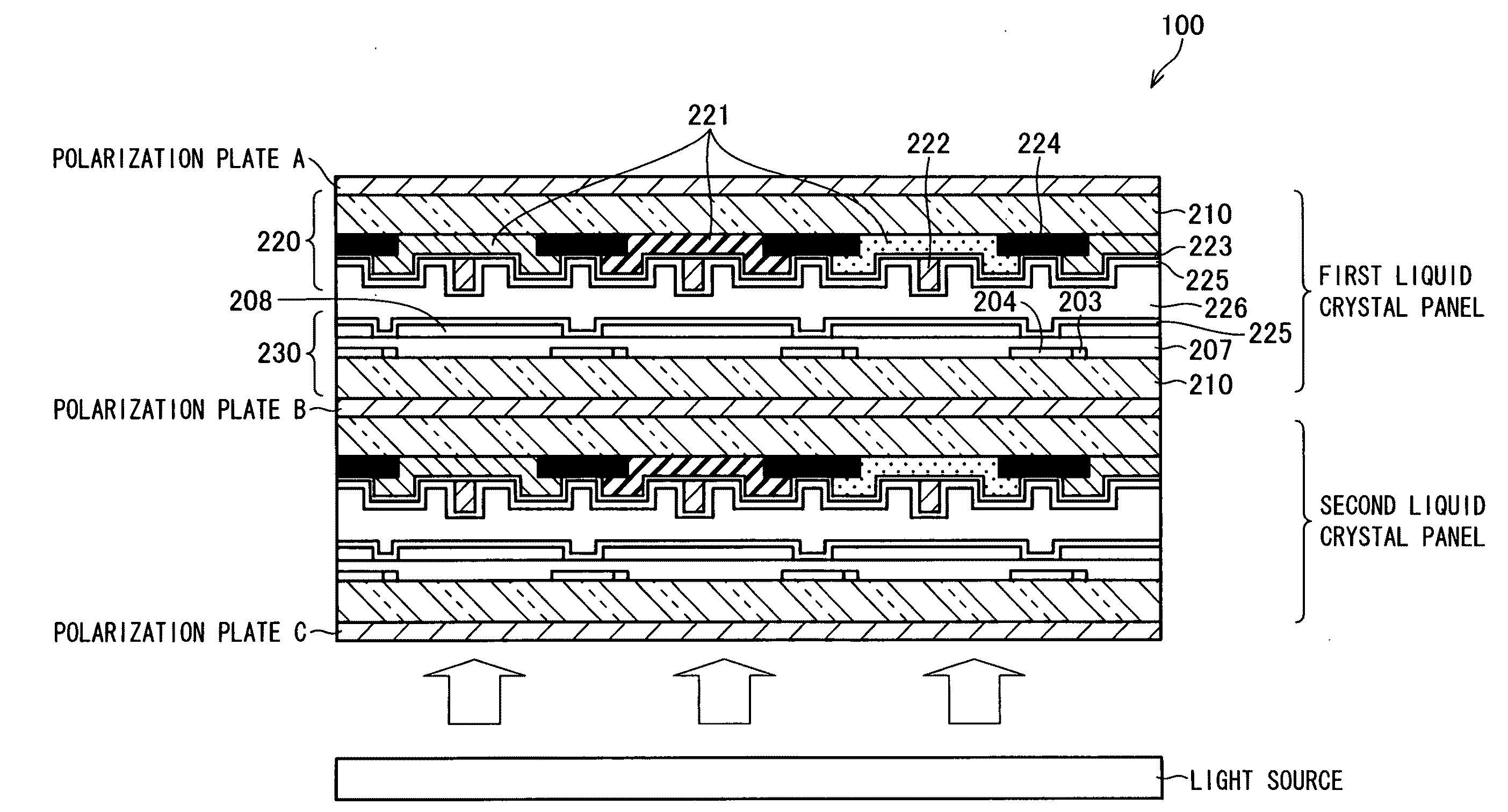
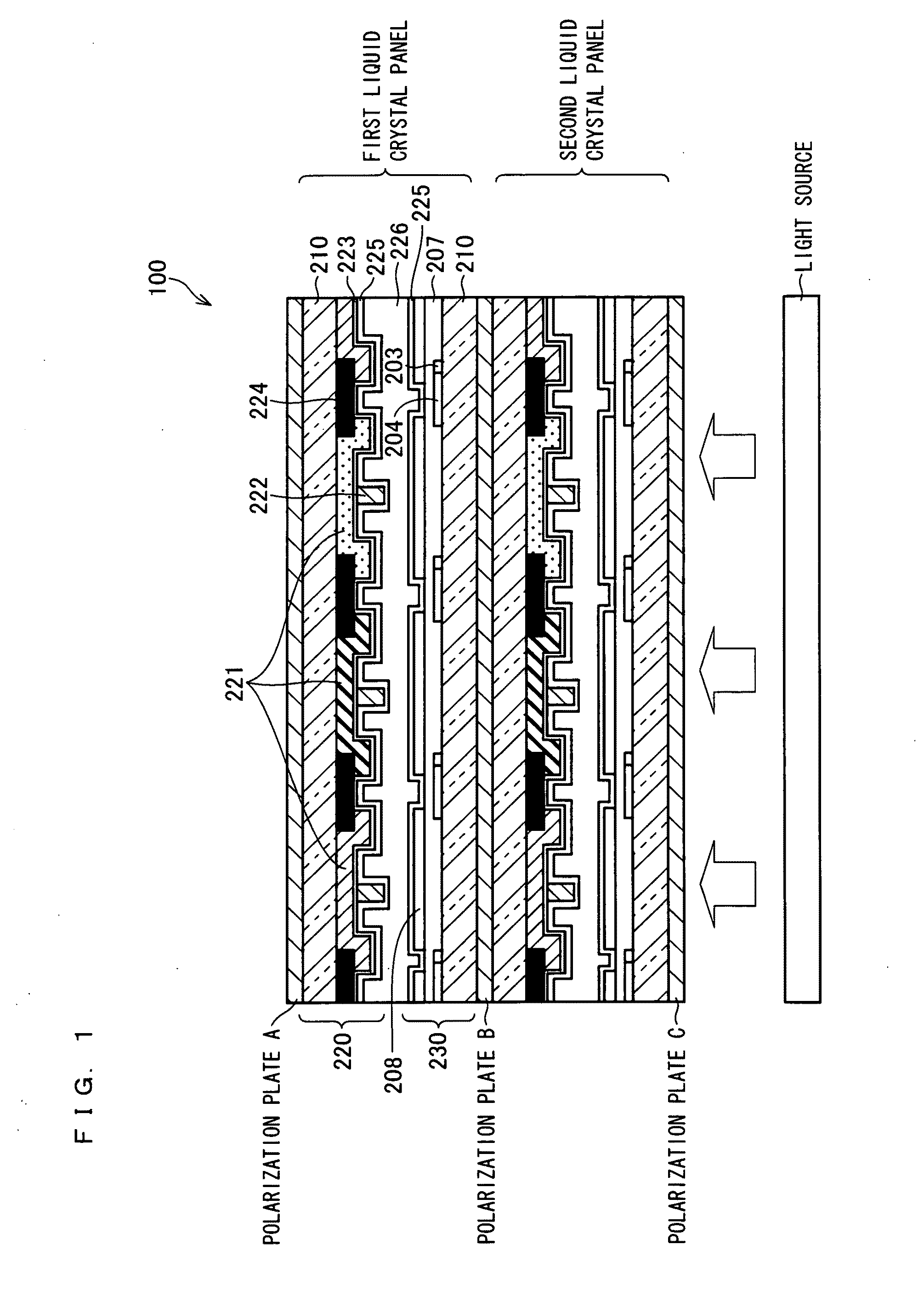
[0075]FIG. 1 is a schematic cross-sectional view illustrating a liquid crystal display apparatus 100 of the present embodiment.

[0076]The liquid crystal display apparatus 100 includes (i) a first liquid crystal panel and a second liquid crystal panel and (ii) polarization plates A, B and C, is arranged such that the panels and the polarization plates are combined alternately as illustrated in FIG. 1. Note that both the first and second liquid crystal panels are transmissive display panels.

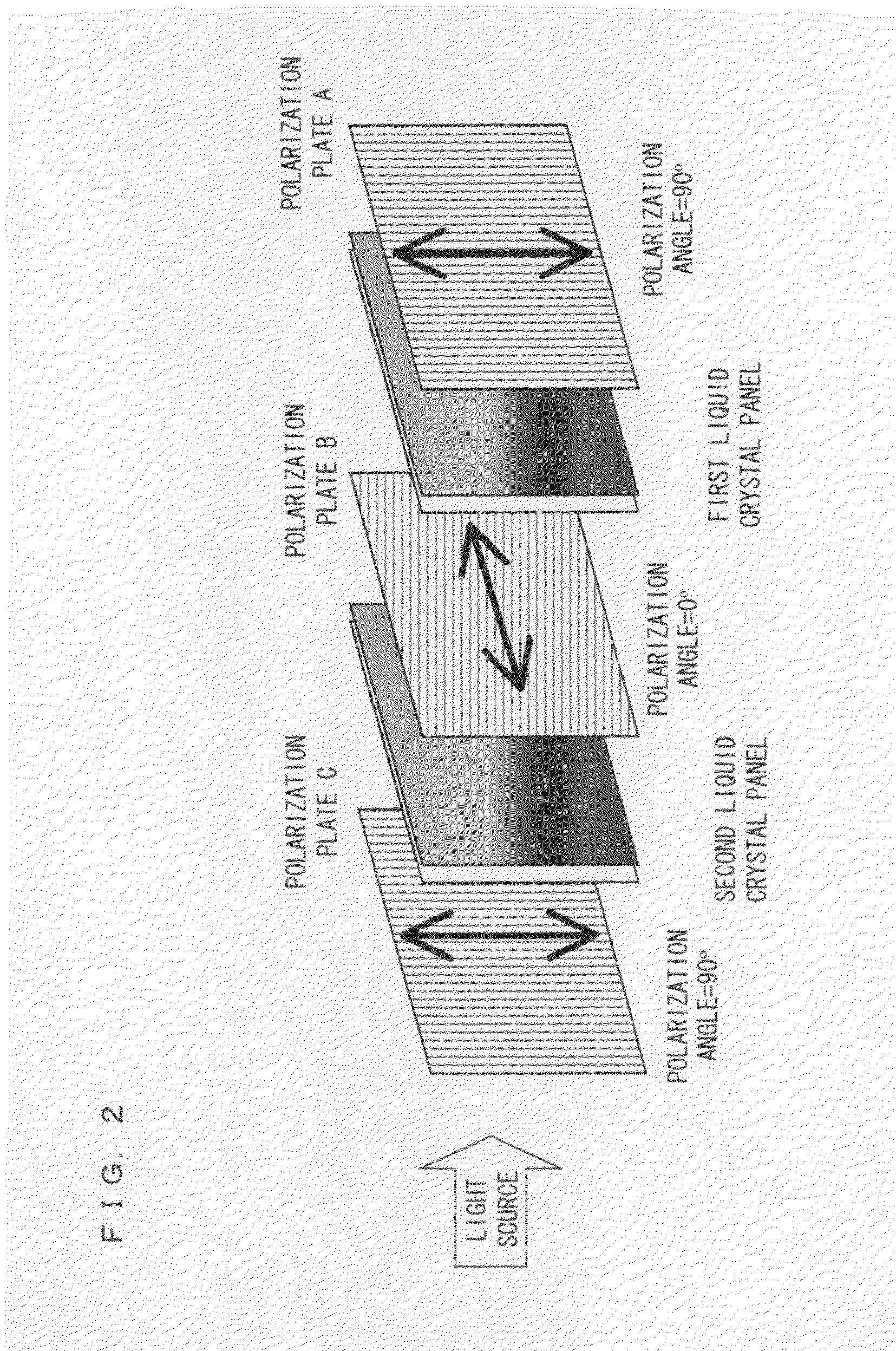
[0077]FIG. 2 is a view illustrating an arrangement of the polarization plates and the liquid crystal panels in the liquid crystal display apparatus 100 illustrated in FIG. 1. In FIG. 2...


PUM


Abstract

In one embodiment of the present invention, a liquid crystal apparatus includes first and second transmissive liquid crystal panels which are combined with each other. Each of the liquid crystal panels displays a video image in accordance with an identical video source. The first liquid crystal panel is driven by an interlace method in which a video image corresponding to one frame is displayed in two fields while the second liquid crystal panel is driven by a progressive method in which a video image corresponding to one frame is displayed in one field. Accordingly, the display apparatus has high display quality and no interference fringes. This attains a liquid crystal display apparatus with high display quality since the liquid crystal display apparatus has no interference fringes even if a plurality of transmissive liquid crystal display panels are combined with each other.

Description

TECHNICAL FIELD[0001]The present invention relates to a display apparatus in which two or more transmissive display panels are combined with each other. In particular, the present invention relates to a display apparatus in which two or more transmissive liquid crystal panels are combined with each other.BACKGROUND ART[0002]There exist various techniques for improving the contrast of a liquid crystal display apparatus. The following examples are disclosed in Patent Literatures 1 through 7.[0003]Patent Literature 1 discloses a technique of improving a contrast ratio by appropriately setting the content and the specific surface area of a yellow pigment in a color filter. According to this technique, pigment molecules of the color filter scatter and depolarize polarized light. This makes it possible to remedy a problem of a decrease in the contrast ratio of a liquid crystal display apparatus. The technique disclosed in Patent Literature 1 reveals that the contrast ratio of a liquid cry...

Claims


Application Information

Patent Timeline
IPC IPC(8): G02F1/1347
CPCG02F1/13471G09G3/3406G09G3/3648G09G2300/023H04N7/012G09G2310/0224G09G2310/0229G09G2340/0435H04N5/66G09G2300/0443
Inventor NAKAMOTO, TATSUYA
Owner SHARP KK
Why Eureka
Try Eureka