Production method of optical element, optical element forming mold and optical element

a production method and technology of optical elements, applied in the field of optical element production methods, optical element forming molds and optical elements, can solve the problems of difficult to supply products which satisfy commercial demands, difficult to allow the commercial availability of optical lenses at low cost, lens surface is subjected to scratches which are optically detrimental, etc., and achieves a wider bonding area and high productivity.

Active Publication Date: 2010-02-11
MAXELL HLDG LTD
View PDF5 Cites 29 Cited by
  • Summary
  • Abstract
  • Description
  • Claims
  • Application Information

AI Technical Summary

Benefits of technology

[0031]According to the present invention, there can be provided a method of producing an optical element with a high productivity.
[0032]Further, according to the present invention, there can be provided an optical element capable of ensuring a wider bonding area.

Problems solved by technology

As a result, it is difficult to allow the optical lens to be commercially available at low costs.
Further, it is difficult to supply products which satisfy commercial demands.
Further, the square lens does not have a member for protecting the lens surface having a convex shape, different from a canned lens which is disposed in a can, and accordingly, there would be caused the risk that the lens surface is subjected to a scratch which is optically detrimental, during handling of the square lens.
The lens with such a scratch cannot be used as a product.
Thus, it is difficult to materialize the reduction in the working man-hours and the like.

Method used


Image

  • Production method of optical element, optical element forming mold and optical element
  • Production method of optical element, optical element forming mold and optical element
  • Production method of optical element, optical element forming mold and optical element

Examples


first embodiment

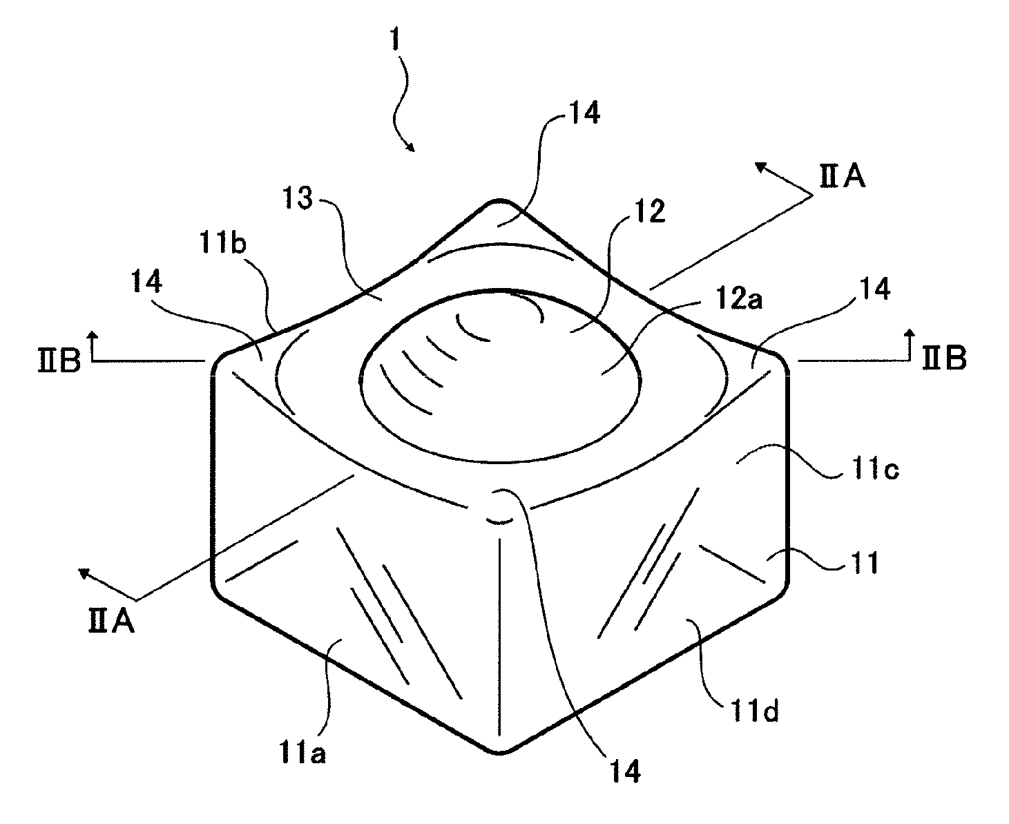
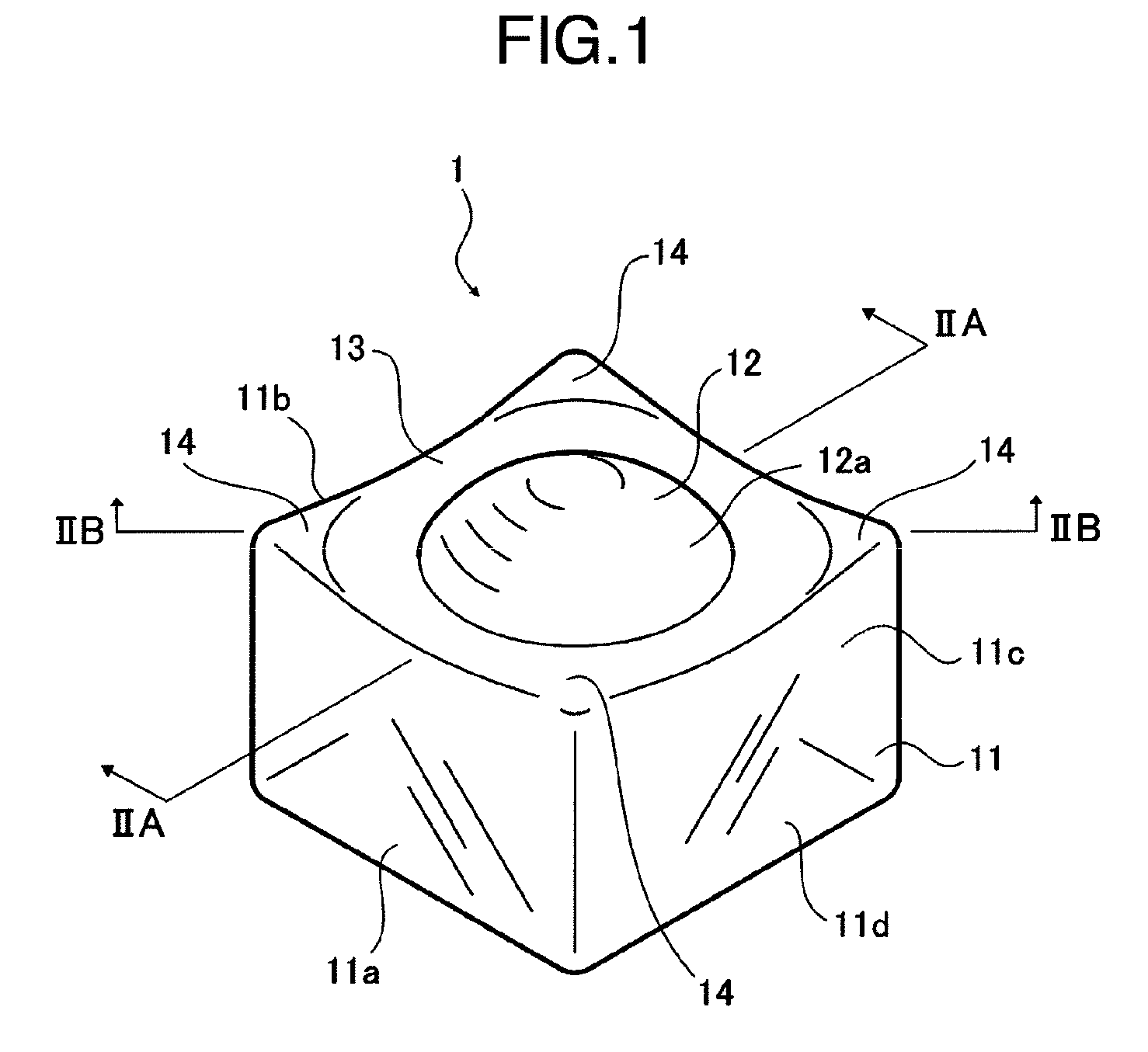
[0034]FIG. 1 is a schematic perspective view which shows an external appearance of an optical element 1 in a first embodiment of the present invention. FIGS. 2A and 2B are longitudinal sectional views which show the optical element 1 shown in FIG. 1, that is, FIG. 2A is a sectional view along line IIA-IIA in FIG. 1, and FIG. 2B is a sectional view along line IIB-IIB in FIG. 1.

[0035]The optical element 1 shown in FIG. 1 incorporates a body portion (quadrate body portion) 11 having a substantially rectangular parallelepiped shape, a lens portion (incident side lens or a first lens portion) 12 having a curved shape lens surface 12a which is formed being protruded from one surface (upper surface) of the body portion 11, a flat part 13 formed in the one surface of the body portion 11, adjacent to the lens portion 12, and the protrusions (bulged portions) which are each formed at four corners of the one surface of the body portion 11, adjacent to the flat part 13.

[0036]Further, the optica...

third embodiment

[0112]FIG. 14 is a perspective view which shows the external appearance of an optical element 1 in a third embodiment of the present invention. Further, FIGS. 15A to 15C are views which shows an projection of the optical element 1 shown in FIG. 14, that is, FIG. 15A is a front view, FIG. 15B is a rear view and FIG. 15C is a plan view. Further, FIG. 16A and FIG. 16B are longitudinal sectional views which show the optical element 1 shown in FIG. 14, that is, FIG. 16A is a sectional view along line XVIA-XVIA in FIG. 15A and FIG. 15B is a sectional view along line XVIB-XVIB in FIG. 15A.

[0113]The optical element 1 shown in FIGS. 14 to 16B is composed of, similar to the first embodiment, a substantially parallelepiped body portion (quadrate body portion) 11, a lens portion (an incident side lens, a first lens portion) 12 having a lens surface 12a of a curved surface shape, which are formed on one surface (front side surface) of the body portion 11 so as to be protruded from the surface th...

fourth embodiment

[0137]FIG. 23 is a perspective view which shows a optical element 1 in a fourth embodiment of the present invention. Further, FIG. 24 is a front view which shows the optical element 1 shown in FIG. 23.

[0138]The optical element 1 shown in FIGS. 23 and 24, includes a quadrate body portion (a quadrangular body portion) 11, a lens portion (incident side lens, first lens portion) 12 having a lens surface 12a in a curved surface shape, which is protruded from one surface (front side surface) of the body portion 11, a flat part 13 which is formed in the one surface of the body portion 11, adjacent to the lens portion 12, protrusions 16 (bulged portions) formed in the one surface of the body portion 11, respectively at the four corners thereof, and a slope portion 15 located between the flat part 13 and the protrusions 14.

[0139]Further, the optical element 1 also includes a lens portion (an emergent side lens, second lens portion) 15 having a lens surface 16a in a curved surface shape, whic...


PUM

PropertyMeasurementUnit
included angleaaaaaaaaaa
shapeaaaaaaaaaa
inter distanceaaaaaaaaaa

Abstract

An optical element being high in productivity and capable of ensuring a large bonding area, and a production method of the optical element. At mold opening when a top part (120) provided with a round portion (121) moves upward, a preform is placed in an inner space the interior of which is formed by a rectangular sleeve (110) and the round portion (131) of a bottom part (130). At mold clamping when the top part (120) moves downward, the preform is pressurized. That is, a convex lens portion is transferred by the concave curved surface (122) and the edge surface (123) of the round portion (121) and the concave curved surface (132) and the edge surface (133) of the round portion (131). The four side surfaces of an optical element (1) are transferred by the inner wall surface (110a) of the sleeve (110). Further, part of the preform jumps out into the gap portion (140) between the outer peripheral surfaces (121a, 131a) of the round portions (121, 131) and the inner wall surface (110a) of the sleeve (110) to thereby form a protrusion portion of the optical element (1). The optical element (1) has a marker (2) formed on the top surface (11a) of its body, and the marker (2) may be formed to extend linearly along the optical axis of lens portions (12, 16). The marker (2) is formed to protrude from the top surface (11a). The side surface (11b) and the side surface (11c) of the body may be formed such that the separating distance between the side surface (11b) and the side surface (11c) gradually increases toward a bottom surface (11d).

Description

TECHNICAL FIELD[0001]The present invention relates to a production method for manufacturing an optical element adapted to be used for optical communication or the like, an optical element forming mold and an optical element.RELATED ART[0002]Heretofore, there has been proposed various methods for manufacturing an optical lens and the like (refer to, for example, JP-A-2005-115148).[0003]In particular, JP-A-2005-115148 discloses a lens element production method in which with the use of a cope mold having a molding surface corresponding to the shape of one of opposite side surfaces of an optical lens, and a drag mold having a molding surface corresponding to the shape of the other of the opposite side surfaces thereof, a glass material or a lens material is disposed between both molding surfaces, and further, an annular holder is located around the molding surface of the drag mold. Further, the method disclosed in JP-A-20005-115148 comprises the steps of heating the glass material so as...

Claims


Application Information

Patent Timeline
Patent Type & Authority Applications(United States)
IPC IPC(8): G02B7/02B29D11/00B28B3/00
CPCC03B11/08C03B2215/404C03B2215/73C03B2215/49Y02P40/57
Inventor SEKI, SHUJIKOMIYA, HIDEKISHIBASAKI, SUSUMUAIHARA, MAKOTOYOSHIMURA, MASASHI
Owner MAXELL HLDG LTD
Why Eureka
Try Eureka