Module for manufacturing electric volatile substance evaporators

a technology of volatile substances and evaporators, which is applied in the direction of steam generation using steam absorption, thermal treatment of fuel, insect catchers and killers, etc., can solve the problems of fan incorporation, type of device, complexity of evaporator devices, etc., and achieves the effect of convenient mounting or assembly

Active Publication Date: 2010-02-11
ZOBELE ESPANA
View PDF15 Cites 1 Cited by
  • Summary
  • Abstract
  • Description
  • Claims
  • Application Information

AI Technical Summary

Benefits of technology

[0010]The present invention satisfactorily solves the previously mentioned drawback by means of the subject matter defined in the attached claims. More specifically the invention relates to a universal module which can be easily mounted or assembled during the manufacture of an evaporator device or different types of standard evaporators. Thus with the module manufacturers can easily incorporate different complements to evaporators which are currently being manufactured without needing to make any substantial modification in the design and with minimum modifications in the assembly process thereof.

Problems solved by technology

In the past few years the complexity of these evaporator devices has increased since different fittings involved in the operation and use of the evaporator have been incorporated.
However one of the more complex modifications of these types of devices is the incorporation of a fan, firstly due to the size thereof and secondly due to the fact that the air flow generated by the fan modifies the temperature of the heating elements and therefore also modifies the evaporation process.
This makes the known evaporators incorporating a fan have a design that is very complex and completely different from standard designs of these types of devices, which logically makes their manufacturing cost increase.
This situation makes producing new evaporators more expensive and slows down the response of manufacturers to their clients' needs and to market demand.
This drawback is accentuated in the case of small manufacturers producing a small number of units each year, and for whom it is very expensive to offer their clients a new evaporator design mainly due to the costs of the molds for the plastic parts, making it difficult to be able to recover the cost of manufacturing a small number of units.

Method used


Image

  • Module for manufacturing electric volatile substance evaporators
  • Module for manufacturing electric volatile substance evaporators
  • Module for manufacturing electric volatile substance evaporators

Examples


Embodiment Construction

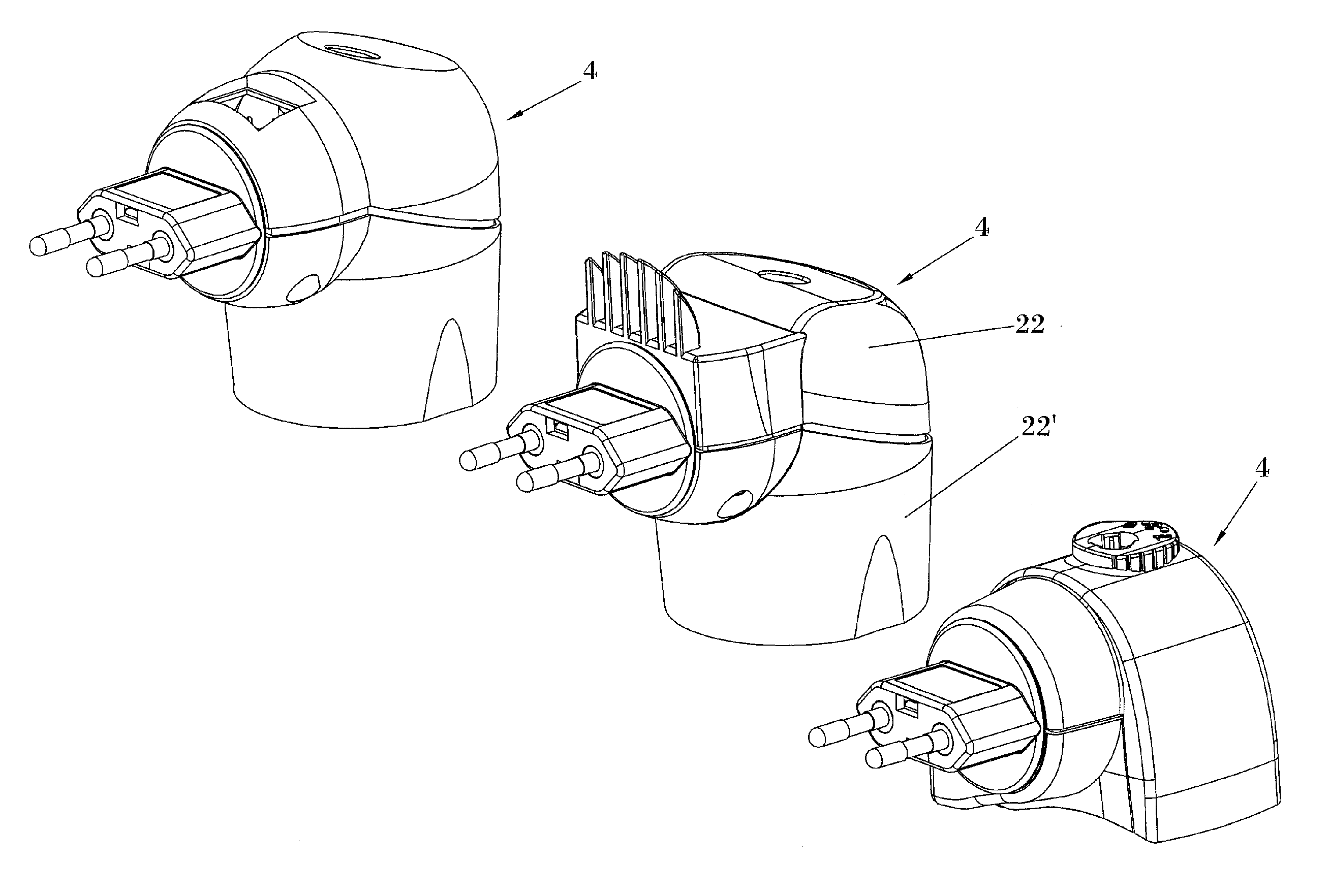
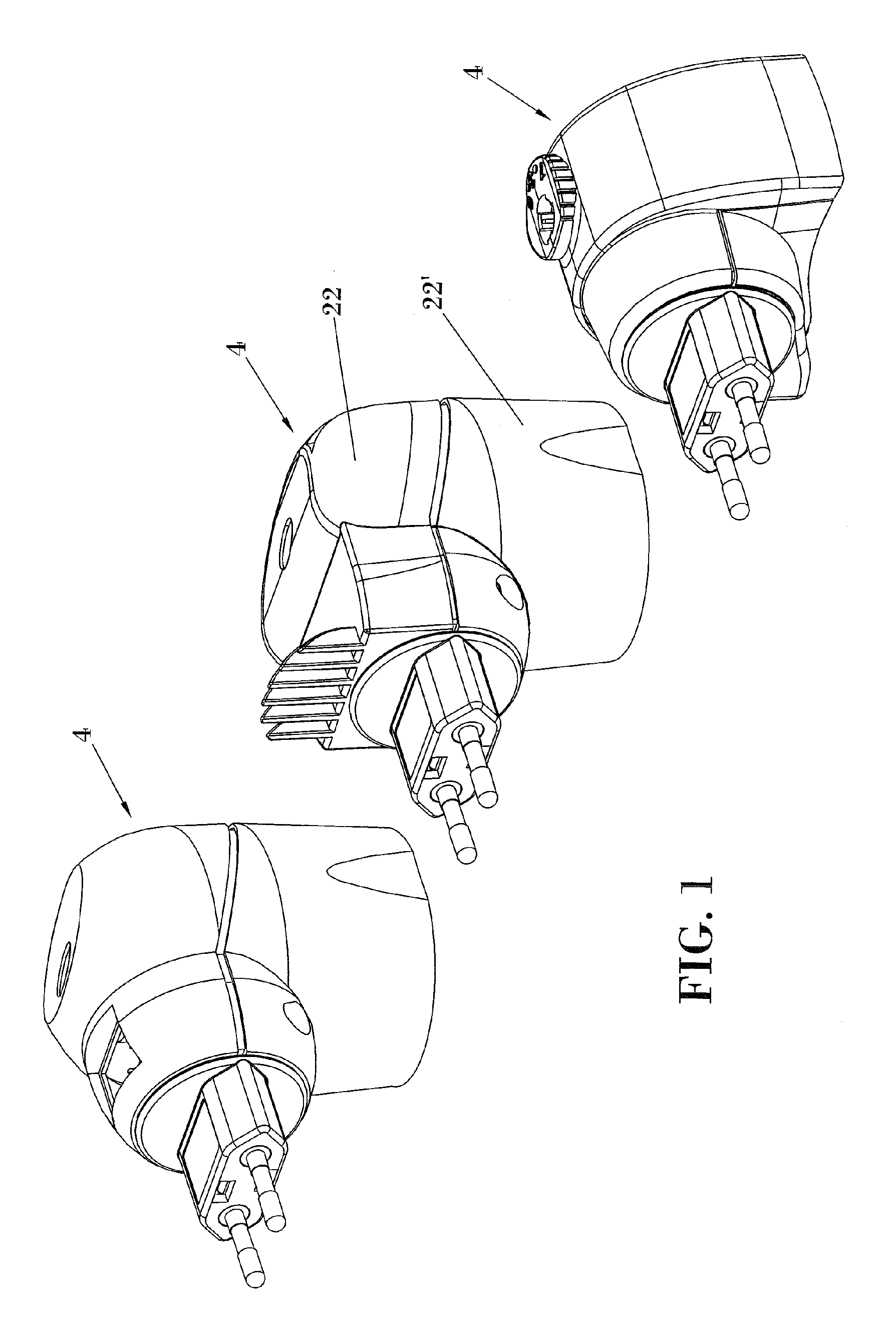
[0022]Three different types of electric volatile substance evaporators are depicted in FIG. 1, in which it can be observed that all of them have in common a standardized inlet for receiving a plug base.

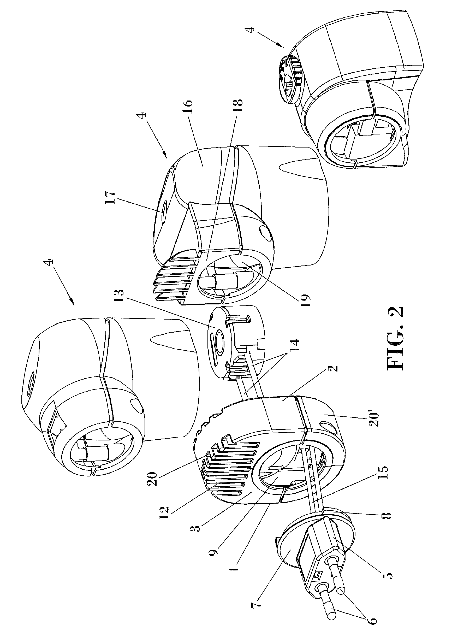
[0023]FIG. 2 shows an embodiment of a module for manufacturing electric volatile substance evaporators formed from a casing (1) in which a first surface (2) which is configured to be assembled with a volatile substance evaporator device (4) is provided. The casing (1) internally carries an electric device, such as a fan or a timer for example, as a complement for the operation of the evaporator.

[0024]The casing (1) further has a second surface (3) intended to receive a plug base (5) having electric terminals (6) for its connection to a mains socket. In the preferred embodiment of FIG. 2, the plug base (5) has a circular platform (7) with a guide section (8) for coupling to the second surface (3) of the casing (1). In this embodiment, the configuration of the second surface (3) for its...


PUM

PropertyMeasurementUnit
electricaaaaaaaaaa
speedaaaaaaaaaa
heating resistancesaaaaaaaaaa

Abstract

The present invention generally relates to manufacturing electric volatile substance evaporators for evaporating aromatic substances and/or insecticides for example and the invention more specifically allows the modular construction of these types of devices such that based on a basic evaporator, a manufacturer of electric evaporators can incorporate additional elements to the device in order to produce different types of evaporators without altering the basic evaporator design, where the module comprises a casing having a first surface configured to be assembled with a volatile substance evaporator and internally carries an electric device intended to cooperate in the operation of the evaporator.

Description

TECHNICAL FIELD OF THE INVENTION[0001]The present invention generally relates to manufacturing electric volatile substance evaporators for evaporating aromatic substances and / or insecticides for example.[0002]More specifically the invention allows the modular construction of these types of devices such that based on a basic evaporator, a manufacturer of electric evaporators can incorporate additional elements to said device in order to produce different types of evaporators without altering the basic evaporator design.[0003]The invention allows a considerable savings in the manufacturing costs of these types of products since a standard evaporator can be used in the manufacture in order to obtain different types of evaporators according to the needs.BRIEF DISCUSSION OF RELATED ART[0004]Electric volatile substance evaporators are widely known in the state of the art and are generally formed of a casing carrying a bottle containing the substance to be evaporated, as well as a wick of ...

Claims


Application Information

Patent Timeline
Patent Type & Authority Applications(United States)
IPC IPC(8): A61L9/03A01M1/20
CPCA01M1/2077H01R35/02H01R13/6658A61L9/037
Inventor CASERTA, ANDREAGARCIA FABREGA, RUBENTOMAS VILARASA, RICARD
Owner ZOBELE ESPANA
Why Eureka
Try Eureka