Spindle device and machining center including the same

a technology of a spindle and a machining center, which is applied in the direction of attachable milling devices, metal-working machine components, manufacturing tools, etc., can solve the problems of increasing downtime, reducing productivity, and taking time to perform maintenance, and achieves short maintenance downtime, high productivity, and replacement in an extremely short time

Active Publication Date: 2010-02-11
NSK LTD +1
View PDF10 Cites 8 Cited by
  • Summary
  • Abstract
  • Description
  • Claims
  • Application Information

AI Technical Summary

Benefits of technology

[0042]According to the present invention, there is provided the wiring extended from the spindle and wired to the support arm via the bracket, and the joint component, provided at a position a predetermined length extended from the extended part of the wiring, is accommodated within the bracket. Therefore, when the spindle is detached from the bracket, the wiring can be disconnected via the joint component while the bracket is kept attached to the support arm. Also, when the spindle is attached to the bracket, the wiring can be connected via the joint component while the bracket is kept attached to the support arm. Thus, the spindle can be replaced in an extremely short time, resulting in short downtime during maintenance and high productivity.
[0043]Further, the joint component is accommodated within the groove portion of the bracket main body, which is covered by the cover. Therefore, when the spindle is detached from the bracket, the joint component can be easily pulled out from the bracket together with the spindle, and the joint component can be prevented from interfering with the other component within the bracket.
[0044]Moreover, the bracket main body is provided with the opening hole penetrating into the groove portion from the rear end face of the bracket main body, and the inclined hole opened from the groove portion to the attachment surface to which the pivot shaft of the support arm is attached. And the wiring is wired to the support arm via the opening hole, the groove portion and the inclined hole of the bracket main body. Therefore, the wiring extended from the spindle can be smoothly wired to the support arm.
[0045]Further, according to the present invention, the bracket to which the spindle is attached is provided with the space through which the first and second wirings are separately wired, and the two opening holes for individually leading the first and second wirings into the space, and therefore, the first and second wirings can be prevented from being influenced by noise. In particular, when the first wiring is a power line for a motor contained in the spindle and the second wiring is a signal line for a sensor, the signal line can be prevented from being influenced by noise caused by the power line. Thus, an operation of the spindle can be accurately detected by the sensor.
[0046]Furthermore, since the space has the first and second spaces formed at substantially symmetry positions with respect to the center axis of the tubular portion of the bracket, the first and second wirings can be wired separately from each other, and each wiring can be prevented from being influenced by noise with more certainty.
[0047]Moreover, with the aim of individually leading out the first and second wirings, the space is opened to a pair of the attachment surfaces to which the pivot shafts of a pair of the support arms are attached, and therefore, the first and second wirings can be wired to the pivot shafts without being influenced by noise.

Problems solved by technology

Thus, for example, when the spindle is detached from the attachment for maintenance, the attachment and the rotary index shaft have to be disassembled in order to disconnect the power line and the signal line via the relay connectors, thereby taking time to perform maintenance.
During maintenance, the machine has to be stopped, and therefore, there arise problems that downtime is increased and productivity is decreased.
Furthermore, when the power line and the signal line are wired together as described in Patent Document 1, the signal line might be influenced by noise from the power line.

Method used


Image

  • Spindle device and machining center including the same
  • Spindle device and machining center including the same
  • Spindle device and machining center including the same

Examples


Embodiment Construction

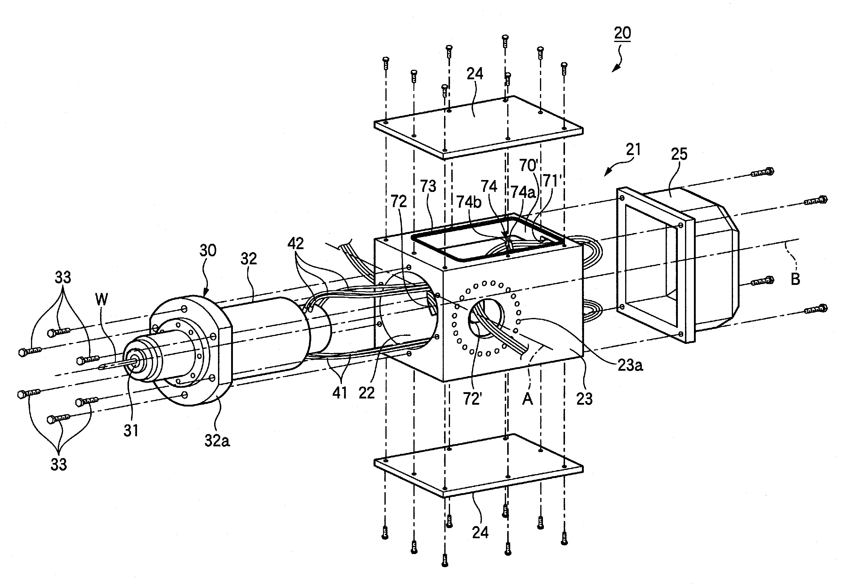
[0070]Hereinafter, a spindle device according to the present invention and a portal machining center, as a machining center according to the present invention, will be described in detail with reference to the drawings.

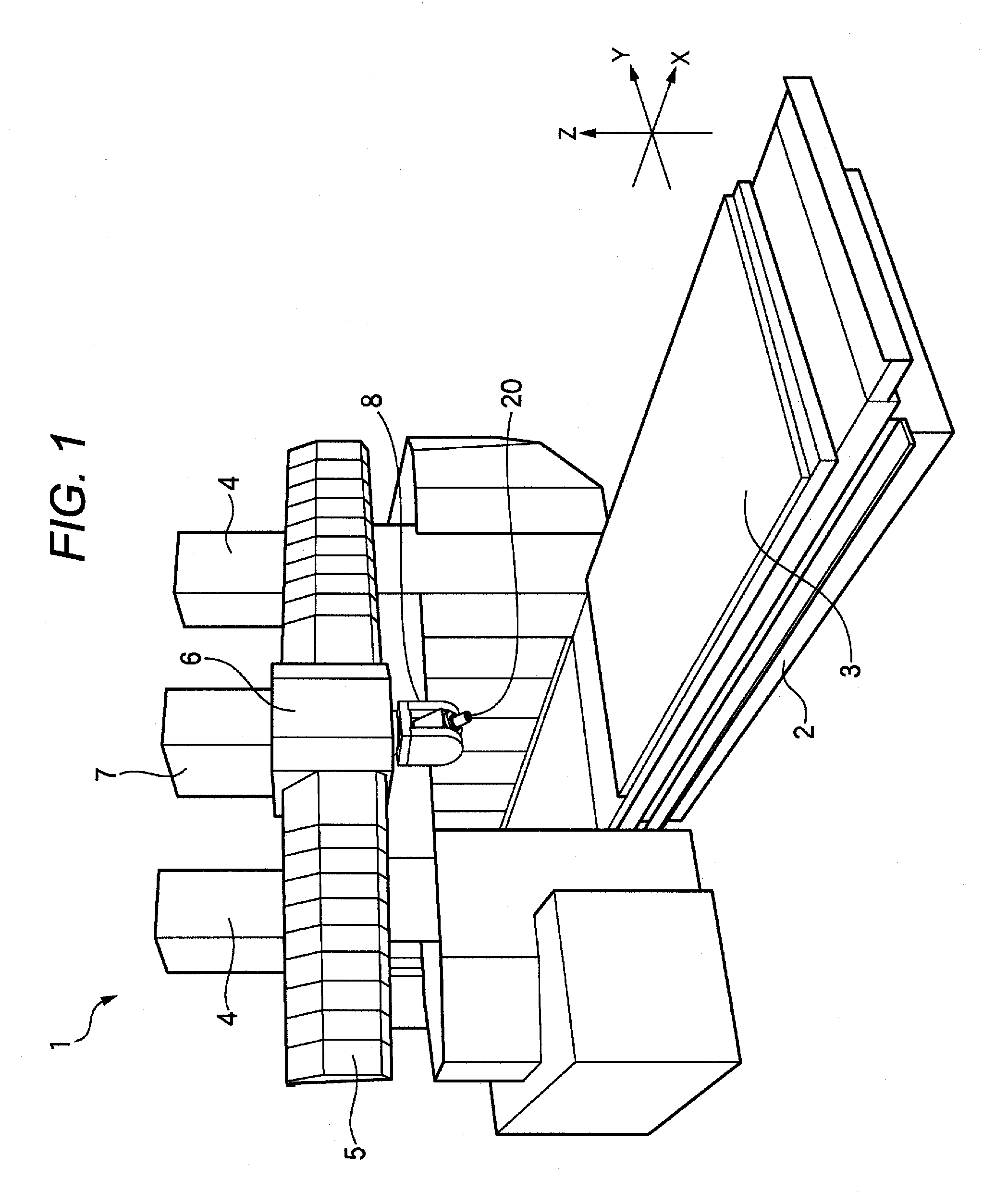
[0071]As shown in FIG. 1, in a portal machining center 1, a table 3 is supported on a bed 2 so as to be movable in an X-axis direction, and a pair of columns 4 are vertically provided on opposite sides of the bed 2. A cross rail 5 is running across upper ends of the columns 4, and a saddle 6 is provided at the cross rail 5 so as to be movable in a Y-axis direction. Further, a ram 7 that can be raised and lowered in a Z-axis direction is supported by the saddle 6, and a spindle head 8 for holding a spindle device 20 of the present invention while allowing driving the spindle device 20 in a rotary index manner around the Y axis and Z axis is fitted to a lower end of the ram 7.

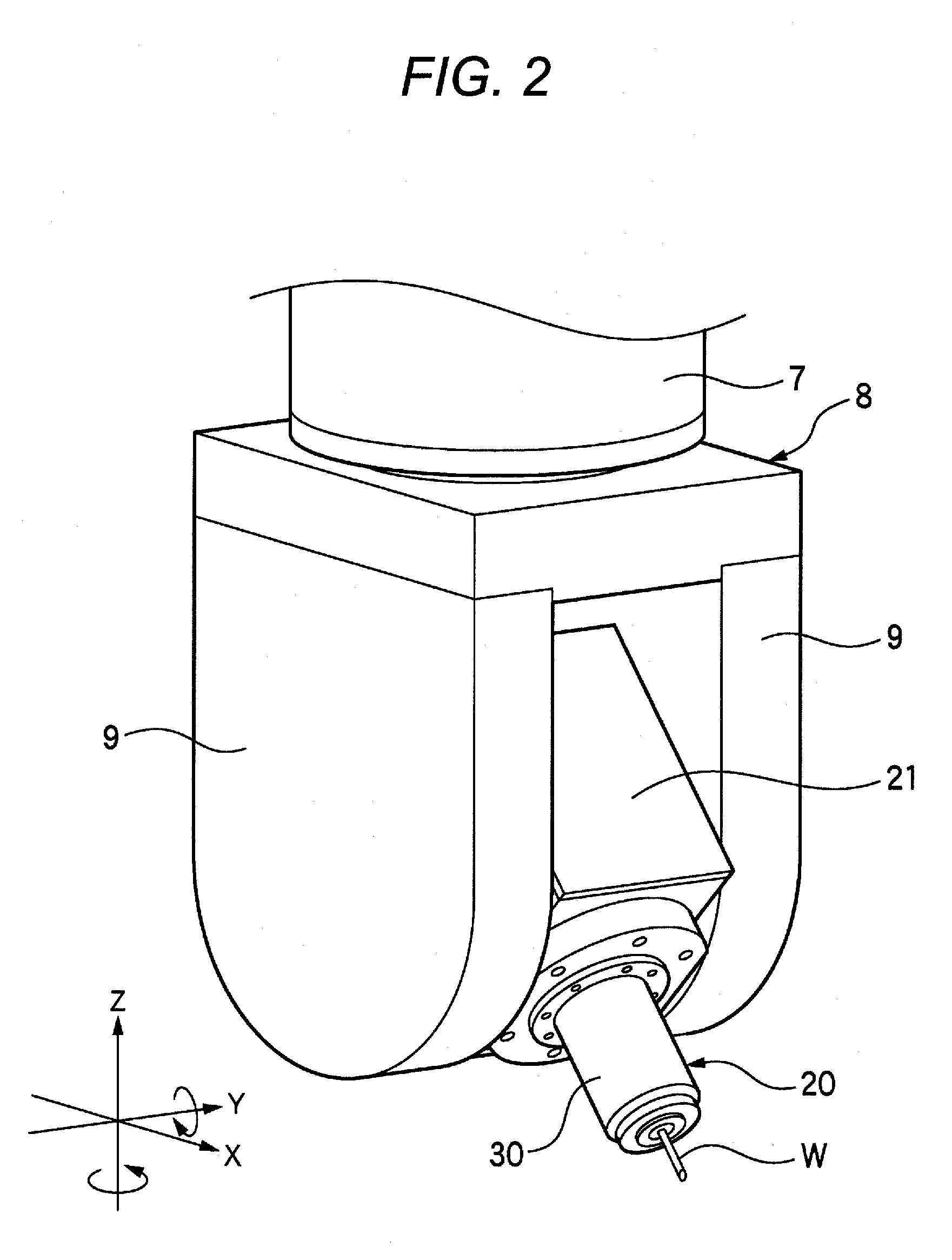
[0072]As shown in FIGS. 2 and 3, the spindle head 8 is provided with a pair of support arms 9 s...


PUM

PropertyMeasurementUnit
lengthaaaaaaaaaa
symmetryaaaaaaaaaa
timeaaaaaaaaaa

Abstract

To provide a spindle device and a machining center, in which spindle replacement can be carried out in an extremely short time, downtime during maintenance is short, and productivity is high. In a spindle device 20, there are provided wirings 41, 42 extended from a spindle 30 and wired to support arms via a bracket 21, and joint components 74, each provided at a position a predetermined length extended from extended parts for the wirings 41, 42, are accommodated within the bracket 21.

Description

BACKGROUND OF THE INVENTION[0001]1. Field of the Invention[0002]The present invention relates to a spindle device and machining center including the spindle devices, and more particularly relates to a spindle device attached to a spindle head of portal machining center and a machining center including the spindle device.[0003]2. Description of Related Art[0004]As a machining center for carrying out working such as cutting and / or drilling by three-dimensional relative movement between a large workpiece and a tool, there has conventionally been used, for example, a portal machining center for causing a straight reciprocating movement of a table to which a workpiece is attached, and for controlling a spindle having a tool in X-axis, Y-axis and Z-axis directions.[0005]In a portal machining center, a saddle is attached to a cross rail supported by two columns, a spindle head is attached to an end of a ram moving in a Z-axis direction with respect to the saddle, and a spindle is pivotably...

Claims


Application Information

Patent Timeline
Patent Type & Authority Applications(United States)
IPC IPC(8): B23Q1/70B23B19/02
CPCB23Q1/0009B23Q1/70Y10T409/307672Y10T409/308288Y10T409/308512Y10T409/309296Y10T409/309352
Inventor YONEYAMA, HIROKIINAGAKI, YOSHIFUMIIWASAKI, OSAMUTATSUDA, YOSHINORI
Owner NSK LTD
Why Eureka
Try Eureka