Device for enhancing efficiency of an energy extraction system

Inactive Publication Date: 2010-02-11
GENERAL ELECTRIC CO
View PDF10 Cites 5 Cited by
  • Summary
  • Abstract
  • Description
  • Claims
  • Application Information

AI Technical Summary

Benefits of technology

[0008]In another embodiment, a method of enhancing efficiency of an energy extraction system utilizing a pressurized flow is provided. The method includes introducing the pressurized flow over a Coanda profile to form a boundary layer and entraining additional fluid flow through the boundary layer to create a high velocity fluid flow. The method also includes generating mechanical work through the high velocity fluid flow.

Problems solved by technology

In certain systems, large and expensive recuperators are employed for recovery of the residual heat.
However, it is relatively expensive to employ such recuperators for recovering this heat in smaller systems.

Method used


Image

  • Device for enhancing efficiency of an energy extraction system
  • Device for enhancing efficiency of an energy extraction system
  • Device for enhancing efficiency of an energy extraction system

Examples


Embodiment Construction

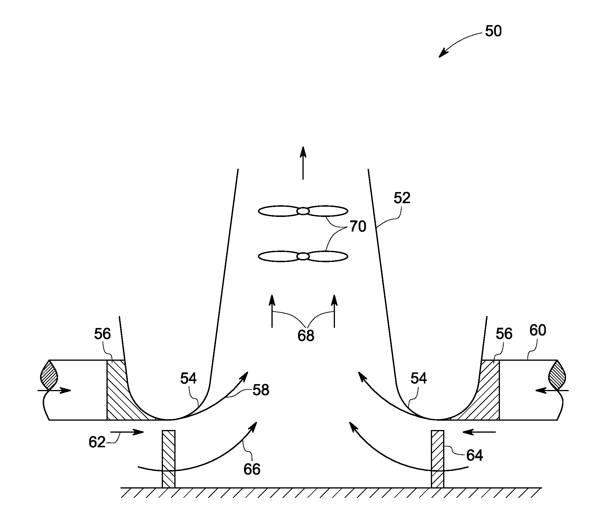
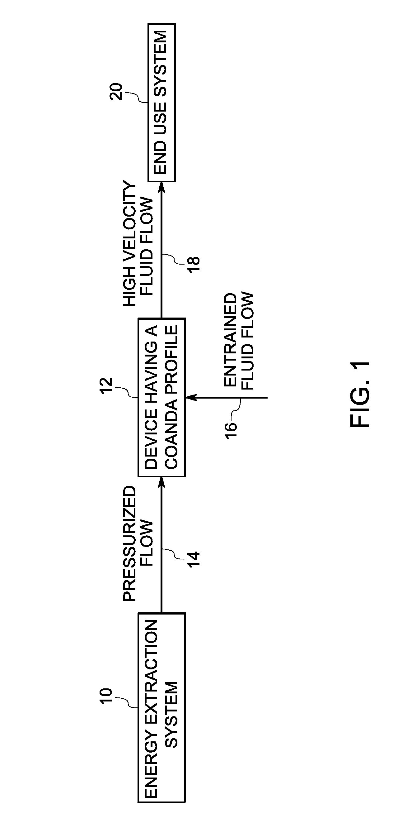
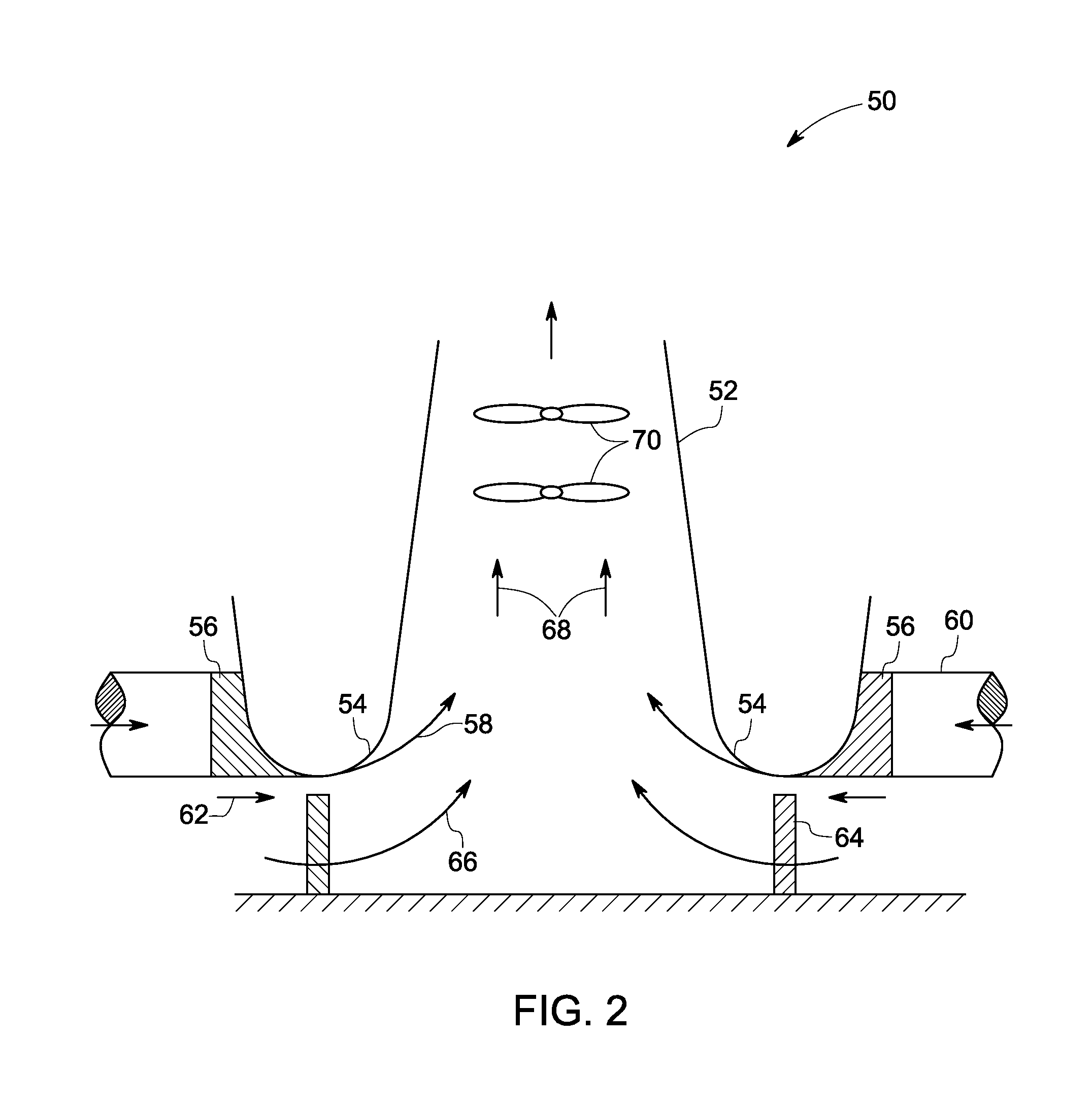
[0020]As discussed in detail below, embodiments of the present technique function to enhance efficiency of certain energy extraction systems such as gas turbine and wind turbine systems by minimizing the heat losses from such systems. In particular, the present technique utilizes the combination of a working fluid and ambient air to generate mechanical work and power. Turning now to the drawings and referring first to FIG. 1 an energy extraction system 10 having a device 12 for recovering heat from the system 10 is illustrated. In the illustrated embodiment, the device 12 is configured to receive a pressurized flow 14 from the energy extraction system 10 and to introduce the pressurized flow along a Coanda profile of the device 12. As used herein, the term “Coanda profile” refers to a profile that is configured to facilitate attachment of a stream of fluid to a nearby surface and to remain attached even when the surface curves away from the original direction of fluid motion.

[0021]I...


PUM


Abstract

A device is provided. The device is configured to introduce a pressurized flow along a Coanda profile and to entrain additional fluid flow to create a high velocity fluid flow; wherein the high velocity fluid flow is directed to an end use system through a flow path in flow communication with the device.

Description

BACKGROUND[0001]The invention relates generally to energy extraction systems, and more particularly, to a device for enhancing efficiency of an energy extraction system.[0002]Various types of energy extraction systems are known and are in use. For example, gas turbines extract energy from a flow of combustion gas and are employed for applications such as power generation, marine propulsion, gas compression, cogeneration, offshore platform power and so forth. Similarly, wind turbines convert kinetic energy of wind into mechanical work for applications such as power generation. Furthermore, internal combustion engines employed in vehicles generate power for driving the vehicle.[0003]Certain energy extraction systems employ Brayton cycle where air is compressed through a compressor and the compressed air is combusted with a fuel in a combustion chamber. Further, hot gases from the combustion chamber are expanded through a turbine or a series of turbines for generating mechanical work. ...

Claims


Application Information

Patent Timeline
IPC IPC(8): F03D1/04
CPCF02K1/28F03D1/04F03D11/00Y02B10/30F05D2270/173Y02E10/722F05B2240/13F03D80/00Y02E10/728F03D9/25F03D9/32Y02E10/72
Inventor EVULET, ANDREI TRISTAN
Owner GENERAL ELECTRIC CO
Why Eureka
Try Eureka