
Sandwich panel

a technology of sandwich and sandpaper, which is applied in the field of sandpaper panels, can solve the problems of insufficient character and achieve the effect of excellent practicality and weight reduction

Active Publication Date: 2010-02-11
JAMCO +1
View PDF7 Cites 8 Cited by
  • Summary
  • Abstract
  • Description
  • Claims
  • Application Information

AI Technical Summary

Benefits of technology

[0005]Since light weight is linked to enhanced fuel economy in aircraft, for example, there has recently been a need for reduced weight of structural materials and interior materials. The type of honeycomb sandwich panel described above in which fiber-reinforced plastic panels are placed on the top and bottom of a honeycomb core is used as a material that enables this weight reduction.
[0007]The present invention was developed as a result of concentrated investigation in view of the foregoing drawbacks, and an object of the present invention is to provide a sandwich panel that has excellent practicality as an inner wall material used in aircraft, for example, whereby the abovementioned requirements of flexural strength, peel strength, and in-plane shear strength can be satisfied while having reduced weight by improving the adhesion between layers of middle material that are formed by laminating a plurality of fiber bodies.
[0016]The present invention structured as described above provides a sandwich panel that has excellent practicality as an inner wall material used in aircraft, for example, whereby the abovementioned flexural strength, peel strength, and in-plane shear strength can be obtained while having reduced weight.

Problems solved by technology

However, these characteristics cannot be made adequate merely by varying the amount of fibers or varying the number of fiber layers that constitute the middle layer.

Method used


Image

  • Sandwich panel
  • Sandwich panel
  • Sandwich panel

Examples


working example

[0031]A specific working example of the present invention will be described based on the drawings.

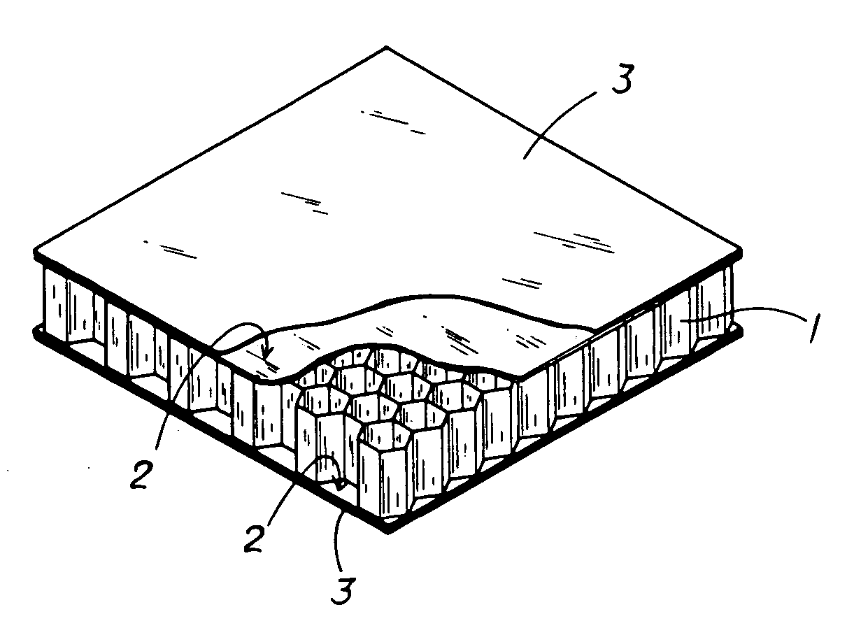
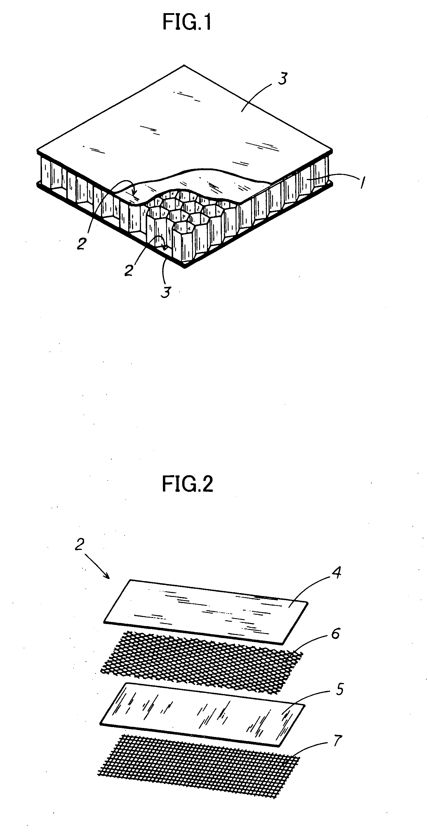
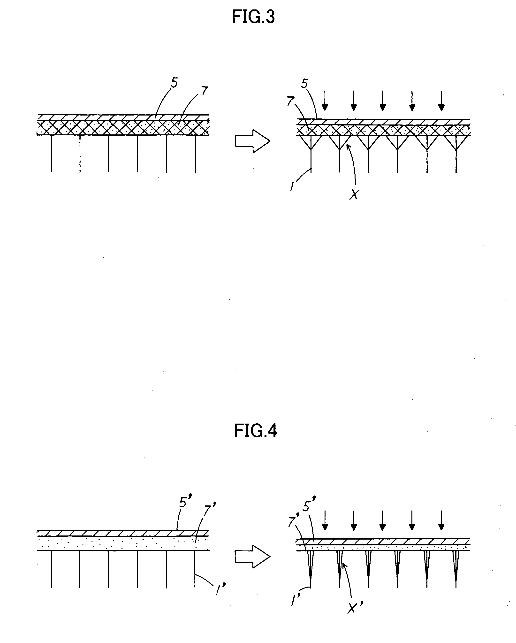
[0032]As shown in FIG. 1, the present working example is a sandwich panel which is square in plan view and in which a middle material 2 and a surface material 3 that are each formed by laminating a plurality of fiber bodies are laminated from inside to outside on the upper and lower surfaces of a hollow columnar core 1, wherein the middle material 2 is composed of a set of unidirectional fiber bodies 4, 5 that are aligned in one direction, the fibers in a first unidirectional fiber body 4 are in a direction that is substantially parallel to an edge of the sandwich panel, the fibers in a second unidirectional fiber body 5 are in a direction that is substantially orthogonal to an edge of the sandwich panel, the resin content ratio of the unidirectional fiber bodies 4, 5 is set to 30% or lower, a first bonding layer 6 having a resin content ratio of 50% or higher is provided between the un...


PUM

PropertyMeasurementUnit
Fractionaaaaaaaaaa
Fractionaaaaaaaaaa
Fractionaaaaaaaaaa

Abstract

A sandwich panel that has excellent practicality as an inner wall material used in aircraft, for example, whereby the abovementioned requirements of flexural strength, peel strength, and in-plane shear strength can be satisfied while having reduced weight. A sandwich panel in which a middle material 2 and a surface material 3 that are each formed by laminating a plurality of fiber bodies are laminated from inside to outside on the upper and lower surfaces of a hollow columnar core 1, wherein the middle material 2 is composed of a set of unidirectional fiber bodies 4, 5 whose fibers are aligned in one direction, bonding layers 6, 7 having a resin content ratio of 50% or higher are provided between the unidirectional fiber bodies 4, 5 and between the hollow columnar core 1 and an inside unidirectional fiber body 5, the bonding layer 7 is composed of a woven fiber body 7 in which fibers are used for a warp yarn and a woof yarn that is orthogonal to the warp yarn, and the yarns are woven, and the woven fiber body 7 is formed so that any one of the warp yarn and the woof yarn is substantially parallel to the edge of the sandwich panel, and the other of the warp yarn and the woof yarn is substantially orthogonal to the edge of the sandwich panel.

Description

BACKGROUND OF THE INVENTION[0001]1. Field of the Invention[0002]The present invention relates to a sandwich panel.[0003]2. Description of the Related Art[0004]The type of honeycomb sandwich panel disclosed in Examined Utility Model Application Publication No. 6-17530 is used conventionally. In this honeycomb sandwich panel, plastic bodies that are reinforced with carbon (C) fiber and used as middle layers are laminated on both the upper and lower surfaces (both open end surfaces) of a honeycomb core that is made of hollow columnar cells aggregated in a plane, and surface members are then laminated on the plastic bodies reinforced with carbon (C) fiber.SUMMARY OF THE INVENTION[0005]Since light weight is linked to enhanced fuel economy in aircraft, for example, there has recently been a need for reduced weight of structural materials and interior materials. The type of honeycomb sandwich panel described above in which fiber-reinforced plastic panels are placed on the top and bottom of...

Claims


Application Information

Patent Timeline
IPC IPC(8): B32B3/12
CPCB32B3/12Y10T428/24942B32B5/024B32B5/12B32B27/12B32B27/304B32B2250/40B32B2260/023B32B2260/046B32B2262/101B32B2262/106B32B2307/50B32B2307/542B32B2307/546B32B2307/718B32B2605/003B32B2605/18Y10T428/236Y10T428/24149B32B5/26Y10T428/249929Y10T428/249939Y10T428/24994Y10T428/3154
Inventor HORIGOME, HIROSHIHIRAI, MASAAKITANAKA, HIROSHI
Owner JAMCO
Learn More