Control apparatus for vehicle

a technology for controlling apparatus and vehicle, applied in the direction of electric control, machines/engines, instruments, etc., can solve the problems of insufficient assurance of the operation reliability of the control system, inability to meet the low cost demand, and increase abnormalities, etc., to achieve the effect of low cos

Active Publication Date: 2010-02-11
DENSO CORP
View PDF12 Cites 34 Cited by
  • Summary
  • Abstract
  • Description
  • Claims
  • Application Information

AI Technical Summary

Benefits of technology

[0011]The present invention addresses the above disadvantages. Thus, it is an objective of the present invention to provide a control apparatus for a vehicle capable of ensuring an operational reliability of a system of the vehicle while satisfying a low cost demand.

Problems solved by technology

Therefore, it cannot meet the low cost demand, which is considered as the important technical goal in these days.
Therefore, in a case where the torque increase abnormality actually exists, there is a high possibility of that such a torque increase abnormality cannot be sensed, and thereby the operational reliability of the control system cannot be sufficiently ensured.
Thus, in such a case, it is not possible to satisfy the low cost demand.

Method used


Image

  • Control apparatus for vehicle
  • Control apparatus for vehicle
  • Control apparatus for vehicle

Examples


Embodiment Construction

[0021]An embodiment of the present invention will be described with reference to the accompanying drawings.

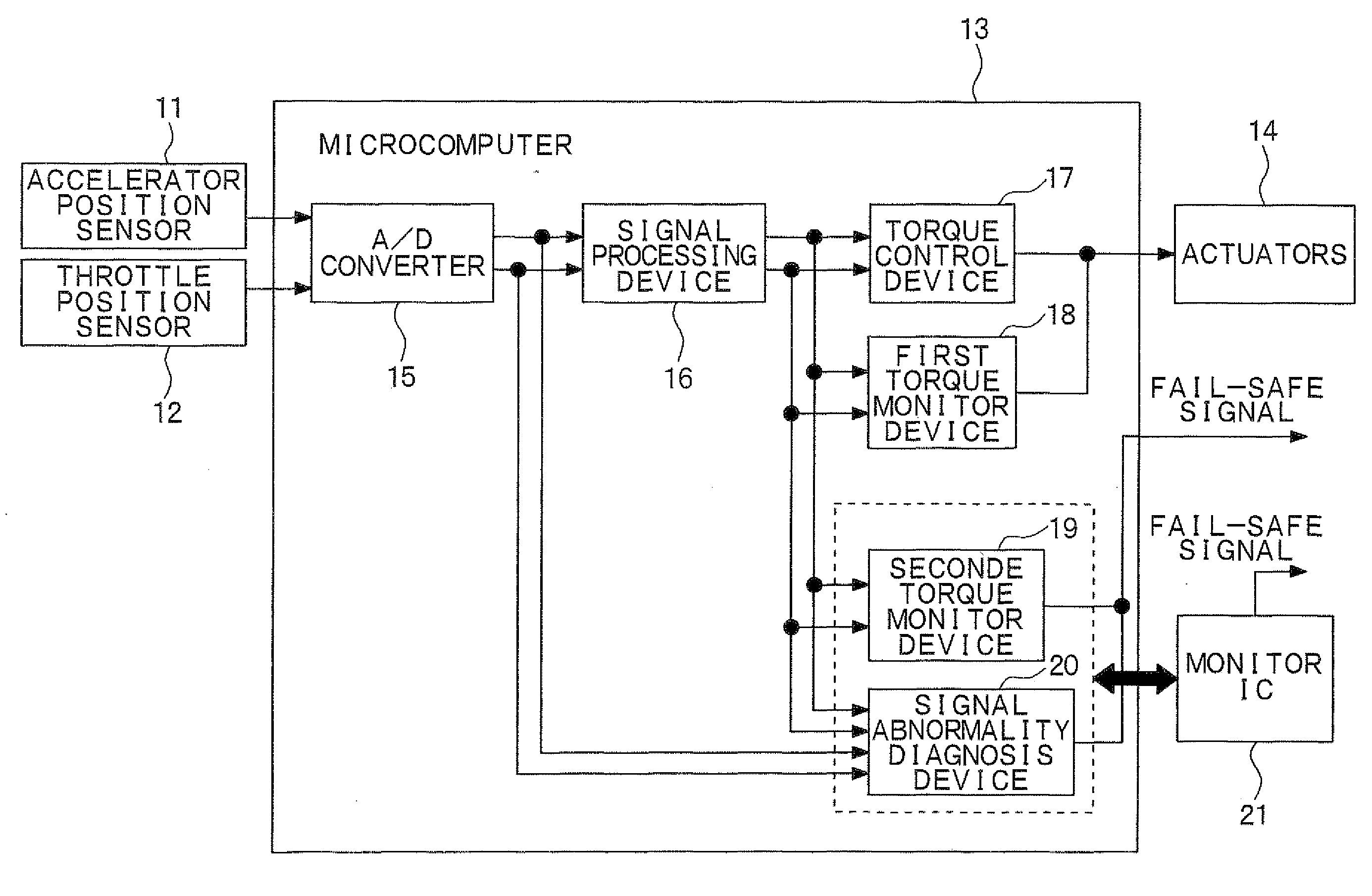
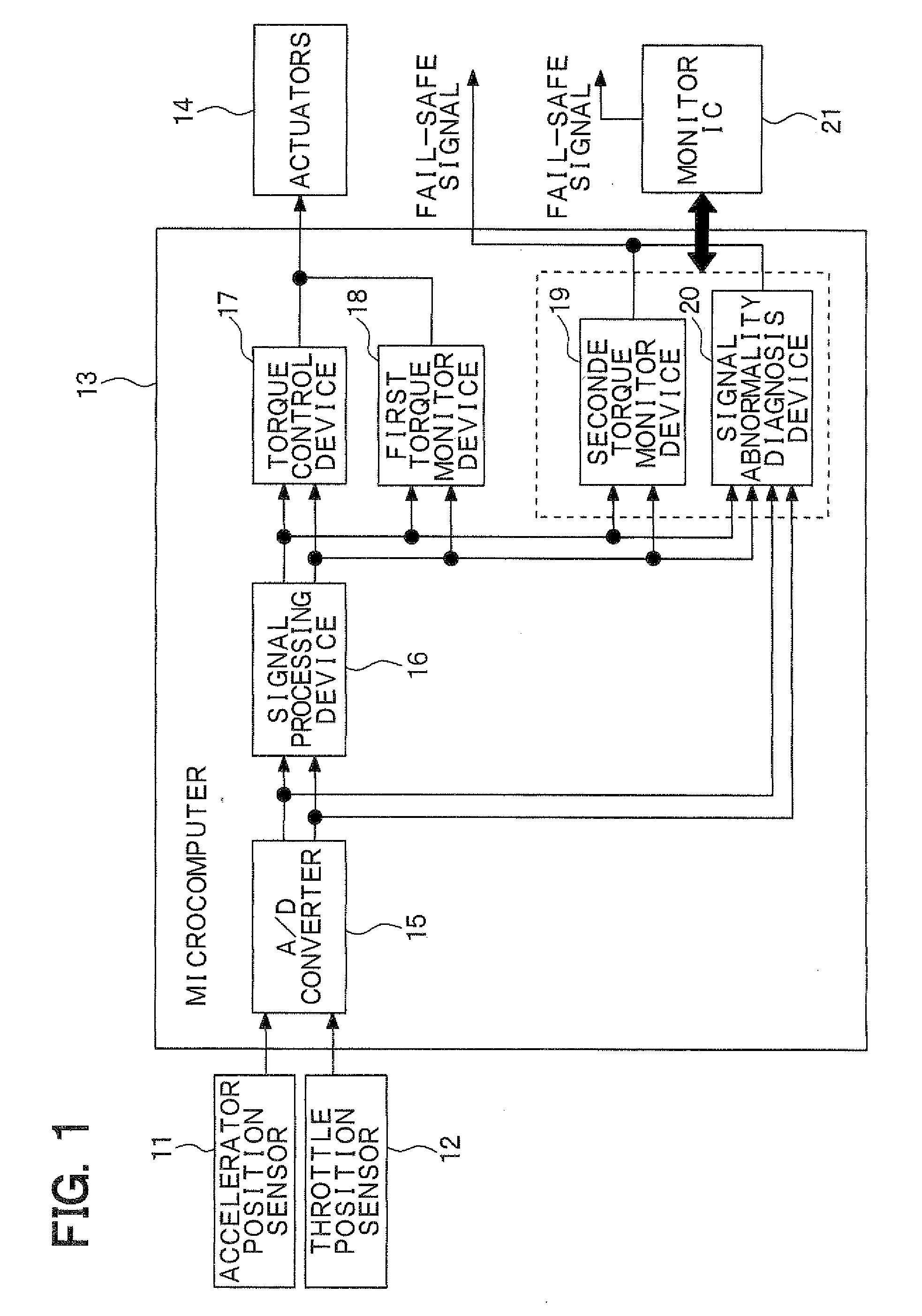
[0022]An entire structure of a torque control system of an internal combustion engine (hereinafter, simple referred to as an engine) will be described with reference to FIG. 1.

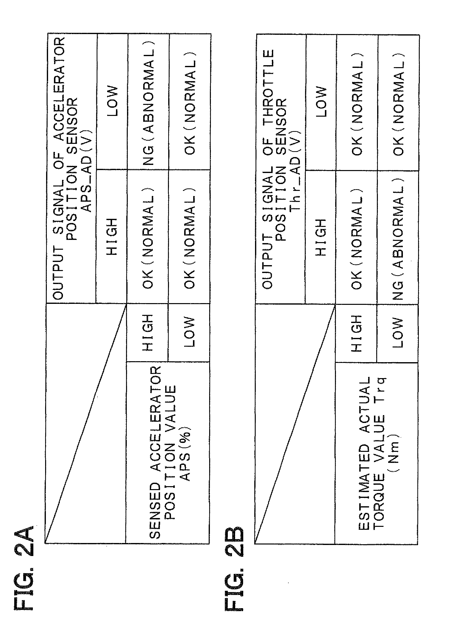
[0023]Output signals of sensors, such as an accelerator position sensor 11 and a throttle position sensor 12, are supplied to a microcomputer 13 (more specifically, a CPU of the microcomputer 13). The accelerator position sensor 11 senses an accelerator position (e.g., a position of an accelerator pedal in an automobile, a position of an accelerator grip in a motorcycle or the like), and the throttle position sensor 12 senses a throttle position (a position of a throttle valve, i.e., an opening degree of the throttle valve). The microcomputer 13 executes various engine control programs stored in a ROM (not shown) to control corresponding actuators 14 (e.g., the throttle valve, a fuel injection valve, a sp...


PUM


Abstract

In a microcomputer, a signal processing device computes a control signal, such as an accelerator position, a throttle position, based on a sensor output signal, such as an output signal of an accelerator position sensor, an output signal of a throttle position sensor. A torque control device executes a torque control operation to coincide an actual torque with a requested torque based on the control signal. Furthermore, a torque monitor device determines whether a torque increase abnormality exists based on the control signal. A signal abnormality diagnosis device determines whether an operational abnormality of the signal processing device exists based on a relationship between the sensor output signal and the control signal. A monitor IC monitors operational states of the torque monitor device and of the signal abnormality diagnosis device and determines whether an operational abnormality of the torque monitor device or of the signal abnormality diagnosis device exists.

Description

CROSS REFERENCE TO RELATED APPLICATION[0001]This application is based on and incorporates herein by reference Japanese Patent Application No. 2008-205953 filed on Aug. 8, 2008.BACKGROUND OF THE INVENTION[0002]1. Field of the Invention[0003]The present invention relates to a control apparatus for a vehicle.[0004]2. Description of Related Art[0005]Nowadays, vehicles are equipped with various electronically controlled systems. For instance, in such a vehicle, as recited in Japanese Unexamined Patent Publication No. H06-149348A, in order to guarantee an operational reliability of the control system, an output signal of a sensor is inputted to two microcomputers, and these two computers execute an identical computation based on the common output signal of the sensor. Then, the computed results of these computers are compared with each other to determine whether an abnormality exists in the control system.[0006]However, according to the technique of Japanese Unexamined Patent Publication ...

Claims


Application Information

Patent Timeline
Patent Type & Authority Applications(United States)
IPC IPC(8): G06F7/00
CPCB60W30/188F02D41/22F02D2250/18F02D2041/227F02D2200/0404F02D41/266
Inventor MURAKAMI, YOSHIFUMI
Owner DENSO CORP
Why Eureka
Try Eureka