Temperature Profiling in an Electricity Meter

a technology of electricity meters and temperature profiles, applied in the field of electric meters, can solve the problems of affecting the service life of the load, so as to reduce the number of failures

Inactive Publication Date: 2010-02-11
LANDIS GYR LLC
View PDF8 Cites 46 Cited by
  • Summary
  • Abstract
  • Description
  • Claims
  • Application Information

AI Technical Summary

Benefits of technology

[0008]At least some embodiments of the present invention address the above described need, as well as others, by profiling the internal temperature of the meter, and/or using information regarding a recorded temperature profile of one or more meters for predictive diagnostics and/or maintenance. Such information may be used to help predict the fai

Problems solved by technology

However, there are conditions that can degrade the condition of a meter, or contribute to the failure of a meter.
When a meter fails, considerable expense is incurred to repair and/or replace the

Method used


Image

  • Temperature Profiling in an Electricity Meter
  • Temperature Profiling in an Electricity Meter
  • Temperature Profiling in an Electricity Meter

Examples


Embodiment Construction

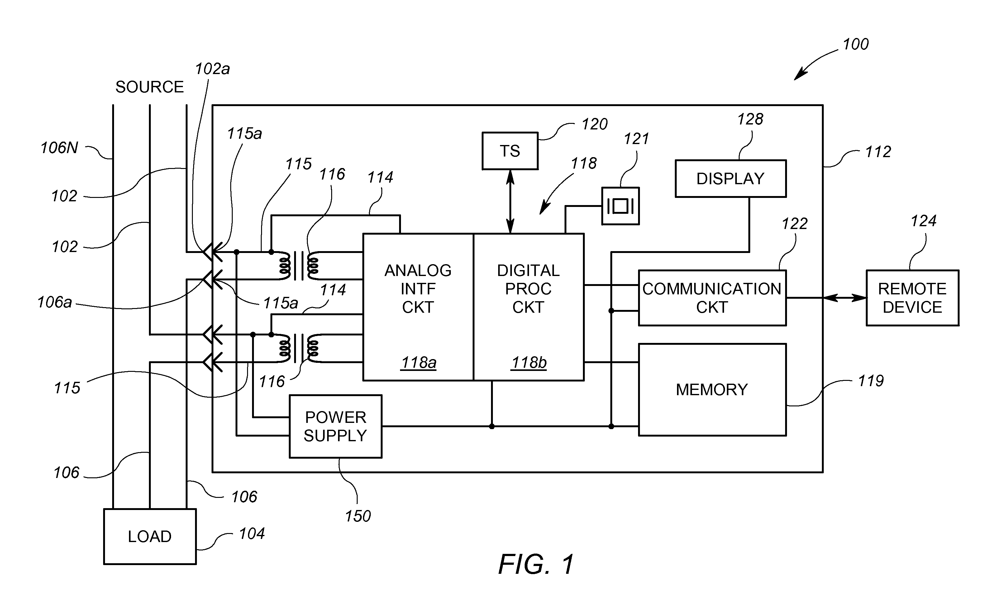
[0020]Referring now to the drawings, and more particularly to FIG. 1, a diagram of an exemplary electrical utility meter 100 constructed according to a first embodiment of the present invention is shown. As shown in FIG. 1, the meter 100 includes a housing 112 in which are disposed first and second current coils 115, first and second current measurement devices 116, voltage measurement devices 114, a processing circuit 118, a memory 119, a temperature sensor 120, a crystal oscillator circuit 121, a communication circuit 122, a display 128, and a power supply 150.

[0021]In FIG. 1, the meter 100 is operably coupled to two utility power lines 102 via first ends of each of the first and second current coils 115. The utility power lines 102 are connected to a source of electricity, such as a utility power transmission and distribution system, not shown. A load 104 (typically a consumer of electrical power) is connected to the power lines 102 through two feeder lines 106. The meter 100 is ...


PUM


Abstract

An arrangement for use in a utility meter includes a temperature sensor, a memory device, a communication circuit, and a processing circuit. The processing circuit is operably coupled to receive information representative of temperature measurements from the temperature sensor. The processing circuit is configured to store first temperature information associated with a first time period in a first data record in the memory device, the first temperature information derived from one or more of the temperature measurements. The processing circuit is further configured to store subsequent temperature information associated with corresponding subsequent time periods in corresponding other data records in the memory device. The processing circuit is also configure to periodically cause the communication circuit to communicate information representative of the first temperature information and the subsequent temperature information to an external device.

Description

[0001]This application claims the benefit of U.S. Provisional Patent Application Ser. No. 61 / 188,228, filed Aug. 7, 2008, and U.S. Provisional Patent Application Ser. No. 61 / 188,247, filed Aug. 7, 2008, both of which are incorporated herein by reference.FIELD OF THE INVENTION [0002]This invention relates generally to electricity meters, and more particularly, electricity meters having a processing circuit.BACKGROUND OF THE INVENTION [0003]Electricity meters are devices that measure and / or meter aspects of energy provided to a load. The load may be a residence, business, or even part of a larger electricity distribution system. Commonly available meters include electromechanical meters and electronic meters. Electromechanical meters employ a rotating disk that rotates in response to electric and magnetic fields induced by the electricity passing to the load. As is known in the art, the disk rotation speed is a function of the amount of electricity delivered to the load. Mechanical co...

Claims


Application Information

Patent Timeline
IPC IPC(8): G01R21/14G06F19/00
CPCG01R22/065G01R31/2849G01R22/10G01K1/14G01R22/068
Inventor MARTIN, WARREN T.VOISINE, JOHN T.
Owner LANDIS GYR LLC
Why Eureka
Try Eureka