Method of operating a rotary beverage bottle or container filling or handling machine with a bearing with a cleaning arrangement in an aseptic clean room in a beverage bottling or container filling plant

a beverage bottle or container filling and handling machine technology, which is applied in the direction of liquid handling, packaging goods types, manufacturing tools, etc., can solve the problems of frequent detection of seal malfunctions, time-consuming and complex inspection and maintenance of conventional sealing systems, and reduce prevent, restrict, and/or minimize substances passing. , the effect of reducing the number of connectors

Active Publication Date: 2010-02-18
KHS GMBH
View PDF17 Cites 14 Cited by
  • Summary
  • Abstract
  • Description
  • Claims
  • Application Information

AI Technical Summary

Benefits of technology

[0010]The object of the present application is to provide a sealing arrangement that has a long service life and essentially ensures and / or promotes a reliable sealing function while also permitting early detection of possible leaks in the system.SUMMARY
[0012]Simply providing two interspaced seals already improves the reliability of the seal. Penetration of an undesired substance from one side of the sealing arrangement to the other can be reliably prevented, restricted and / or minimized by the additional arrangement of a chamber for receiving a barrier medium between the seals. To defeat the entire sealing arrangement, the substance would have to also pass through the chamber with the barrier medium after penetrating the first seal ring. The barrier medium prevents, restricts and / or minimizes penetration in a variety of ways as a function of the embodiment of the present application. In one embodiment, the barrier medium can exhibit a positive pressure relative to that prevailing in the areas adjacent to the sealing arrangement, for example. This alone reliably prevents, restricts and / or minimizes the penetration of undesired substances into the sealing arrangement, since in the event of leaks in one of the two seals the barrier medium is forced through the seal and thus no undesired substance can penetrate through the seal.
[0015]Possible barrier media are liquids or gases that, depending on the application, could have sterilizing properties so that, in cleanroom applications, any germs that penetrate the chamber are killed immediately or substantially immediately to prevent, restrict, and / or minimize contamination of the cleanroom with biologically active substances.
[0016]With a rotary distributor according to the present application, sealing arrangements according to the present application are provided between the individual distribution chambers. The distribution chambers are typically essentially annular, arranged between the stationary and the rotary part of the rotary distributor and have a port to the outside on the stationary part, through which a liquid or gaseous substance is admitted to the annular space. This in turn has in the rotary part one or more tubular connections to one or possibly both free ends of the rotary part. In this manner, the substances admitted in the stationary part can be passed through the annular space to ports on the rotary part, from where they are extracted. Of course, transport can also occur in the opposite direction. In many applications, such a rotary distributor is used to pass a plurality of different substances from the stationary to the rotary part of the distributor. To this end, multiple annular chambers are arranged adjacent to one another in the axial direction, and each is provided with one or more connectors on the stationary side and the rotary part. For reasons of space, these are mostly arranged in the form of a star around the distributor. At least one sealing arrangement according to the present application is provided between the annular spaces of the distributor to seal these from one another. This can reliably prevent, restrict, and / or minimize substances passing from one annular space to another and thus the mixing of the respective substances.
[0017]In one embodiment, two or more sealing arrangements can be provided between two annular distribution chambers, between which sealing arrangements an additional empty chamber is provided, which in this embodiment can also be connected to the outside. This allows for the timely detection of leaks, since some of the barrier medium or a mixture of barrier medium and the substance in the adjacent distribution chamber can penetrate the empty space and be detected via the port to the outside.
[0018]In another embodiment of the rotary distributor according to the present application, all or some of the chambers with the barrier medium can be interconnected and thus share inlets and outlets for the barrier medium to reduce the number of connectors. Even if different barrier media is used in different sections of the sealing arrangement, at least some of the chambers can be interconnected.

Problems solved by technology

Conventional sealing systems for pivot bearing devices often do not fulfill the required and / or desired specifications for this with respect to tightness and long-term resistance of the seal.
Furthermore, the inspection and maintenance of conventional sealing systems is time-consuming and complex, and typically requires and / or desires the dismantling of the connection to determine whether a seal is still sufficiently functional.
In addition, seal malfunctions regularly can be detected when contamination of the cleanroom area is well advanced, possibly having already rendered large portions of the containers handled therein unusable.
If a contaminant should enter the chamber through one seal, the contaminant is drawn into the reservoir and thus could not penetrate the sealing arrangement.

Method used


Image

  • Method of operating a rotary beverage bottle or container filling or handling machine with a bearing with a cleaning arrangement in an aseptic clean room in a beverage bottling or container filling plant
  • Method of operating a rotary beverage bottle or container filling or handling machine with a bearing with a cleaning arrangement in an aseptic clean room in a beverage bottling or container filling plant
  • Method of operating a rotary beverage bottle or container filling or handling machine with a bearing with a cleaning arrangement in an aseptic clean room in a beverage bottling or container filling plant

Examples


Embodiment Construction

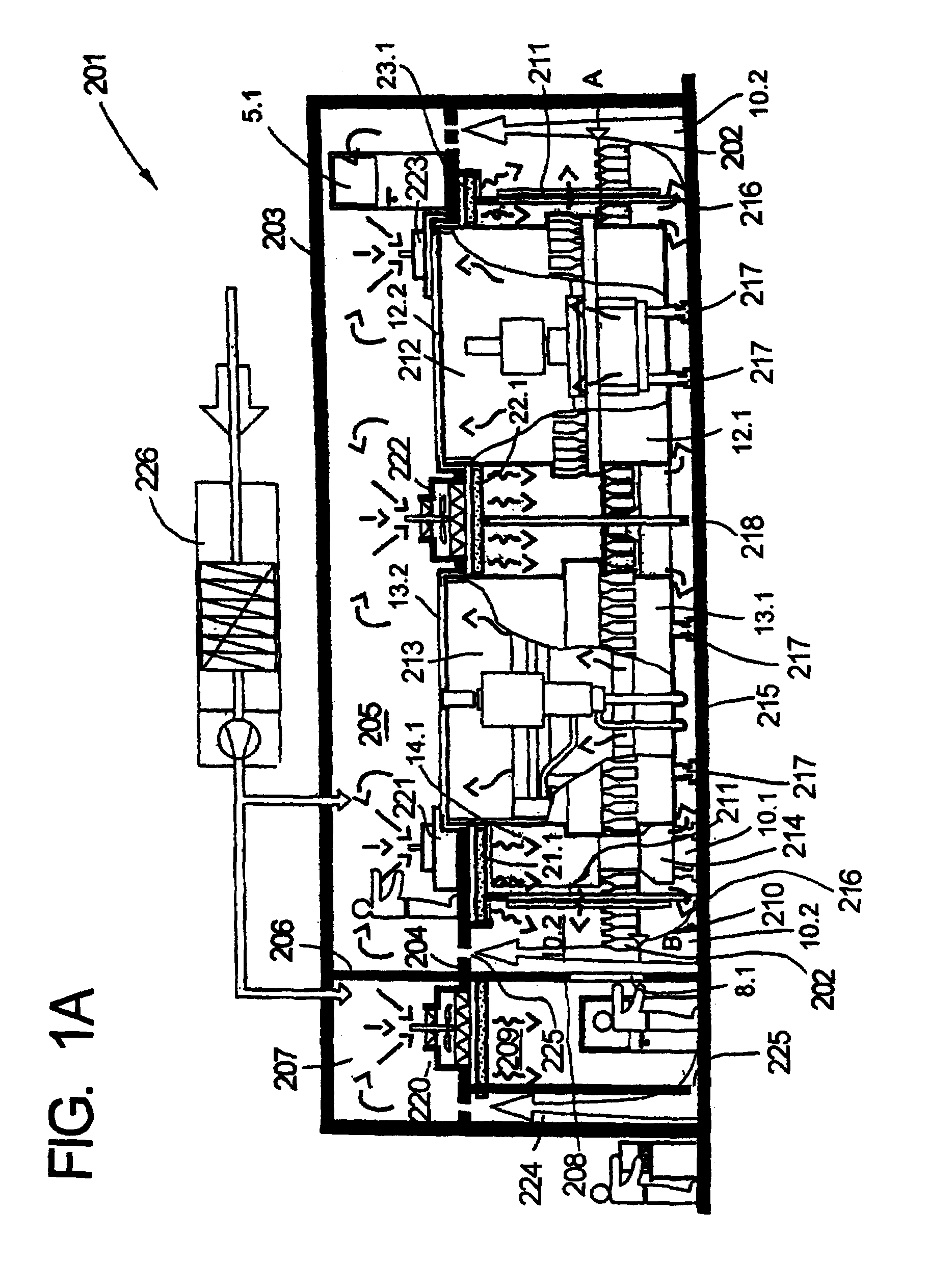
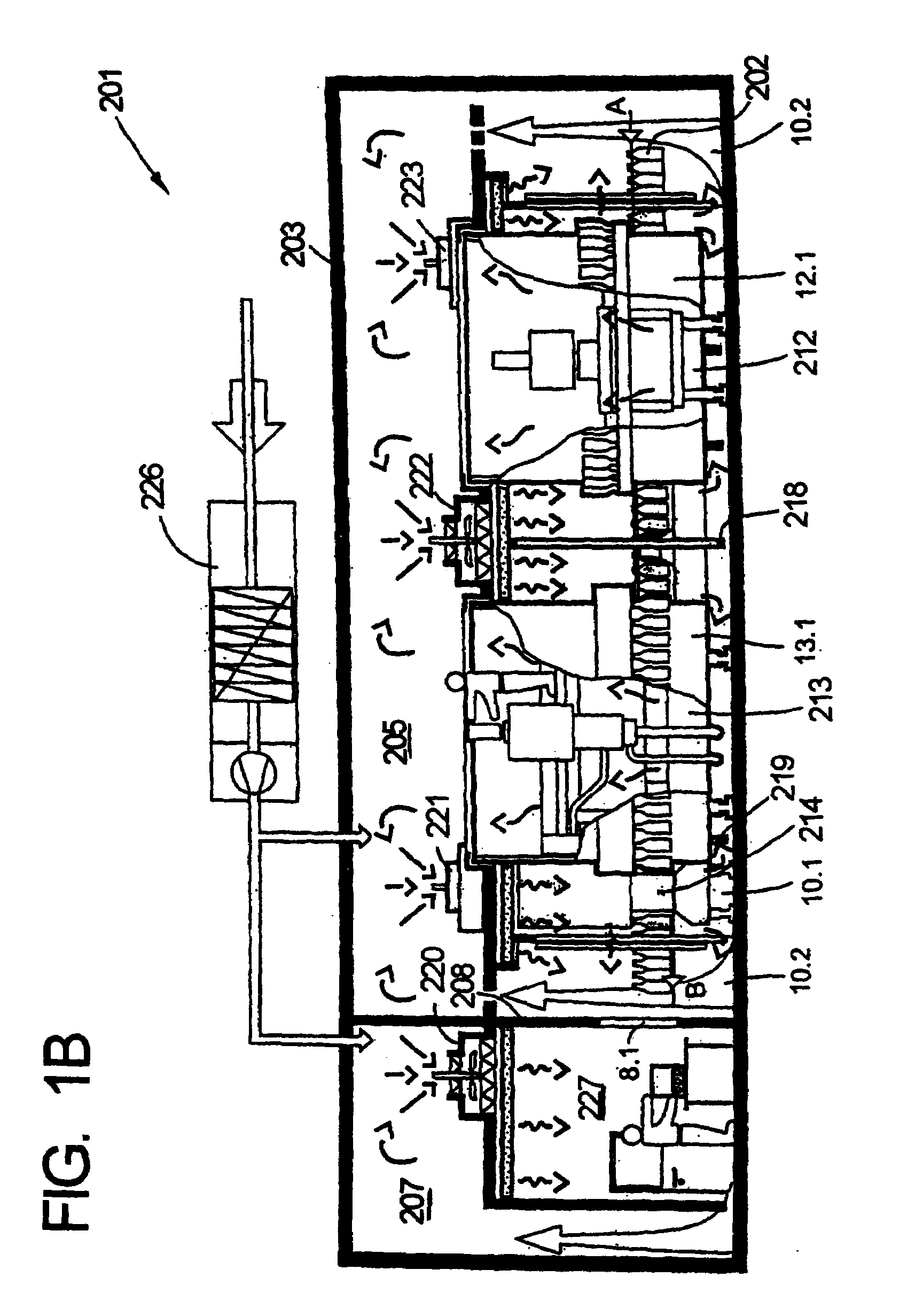
[0033]The plant designated 201 in general in FIGS. 1A-1C is used for the aseptic bottling of a liquid in containers or bottles under clean room conditions, for example of a sensitive and / or highly perishable liquid such as a milk product, fruit juice or similar product, for example, or for the bottling of pharmaceutical products.

[0034]Please note that reference numeral 204 is referred to as both a “false floor” and a “false ceiling.” To clarify, reference numeral 204 is referred to as a “false floor” when the upper portion of the below described bottling plant is being referred to, that is, when reference numeral 204 acts essentially as a floor. In contrast, reference numeral 204 is referred to as a “false ceiling” when the lower portion of the below described bottling plant is being referred to, that is, when reference numeral 204 acts essentially as a ceiling.

[0035]The plant 201 comprises essentially an outer housing 203 which encloses an interior which is essentially tightly clos...


PUM

PropertyMeasurementUnit
pressure monitoraaaaaaaaaa
pressureaaaaaaaaaa
long-term resistanceaaaaaaaaaa

Abstract

A method of operating a rotary beverage bottle or container filling or handling machine with a bearing with a cleaning arrangement in an aseptic clean room in a beverage bottling or container filling plant. The abstract of the disclosure is submitted herewith as required by 37 C.F.R. §1.72(b). As stated in 37 C.F.R. §1.72(b): A brief abstract of the technical disclosure in the specification must commence on a separate sheet, preferably following the claims, under the heading “Abstract of the Disclosure.” The purpose of the abstract is to enable the Patent and Trademark Office and the public generally to determine quickly from a cursory inspection the nature and gist of the technical disclosure. The abstract shall not be used for interpreting the scope of the claims. Therefore, any statements made relating to the abstract are not intended to limit the claims in any manner and should not be interpreted as limiting the claims in any manner.

Description

CONTINUING APPLICATION DATA[0001]This application is a Continuation-In-Part application of International Patent Application No. PCT / EP2007 / 007191, filed on Aug. 15, 2007, which claims priority from Federal Republic of Germany Patent Application No. 10 2006 038 747.3, filed on Aug. 17, 2006. International Patent Application No. PCT / EP2007 / 007191 was pending as of the filing date of this application. The United States was an elected state in International Patent Application No. PCT / EP2007 / 007191.BACKGROUND[0002]1. Technical Field[0003]The present application relates to a method of operating a rotary beverage bottle or container filling or handling machine with a bearing with a cleaning arrangement in an aseptic clean room in a beverage bottling or container filling plant, and to a sealing arrangement for a pivot bearing device comprising a stationary part, a rotary part and a rotary distributor.[0004]2. Background Information[0005]Background information is for informational purposes o...

Claims


Application Information

Patent Timeline
Patent Type & Authority Applications(United States)
IPC IPC(8): B67C3/22B23P6/00
CPCB67C3/22F16J15/002Y10T29/49719F16J15/40F16J15/004
Inventor NEUMANN, BERNDBESTMANN, MATTHIAS
Owner KHS GMBH
Why Eureka
Try Eureka