Umbilical termination assemblies

a technology of umbilical termination and assembly, which is applied in the direction of coupling device connection, survey, borehole/well accessories, etc., can solve the problems of expensive process, and achieve the effect of reducing the work required, faster installation and cheaper

Inactive Publication Date: 2010-02-18
GE OIL & GAS UK LTD
View PDF11 Cites 18 Cited by
  • Summary
  • Abstract
  • Description
  • Claims
  • Application Information

AI Technical Summary

Benefits of technology

[0005]The invention substantially reduces the work required by an ROV during the installation process by elimination of the need for a foundation framework with its stab and funnel and also eliminates, or at least reduces, the need for bend restrictors, thus making installation quicker and cheaper.
[0017]allowing the assembly to rotate relative to the at least one foundation so that said one of the limbs is horizontally disposed, for example with a portion of the umbilical laying on said bed.

Problems solved by technology

The above sequence of operations involves substantial use of an ROV, which is an expensive process.

Method used


Image

  • Umbilical termination assemblies
  • Umbilical termination assemblies
  • Umbilical termination assemblies

Examples


Embodiment Construction

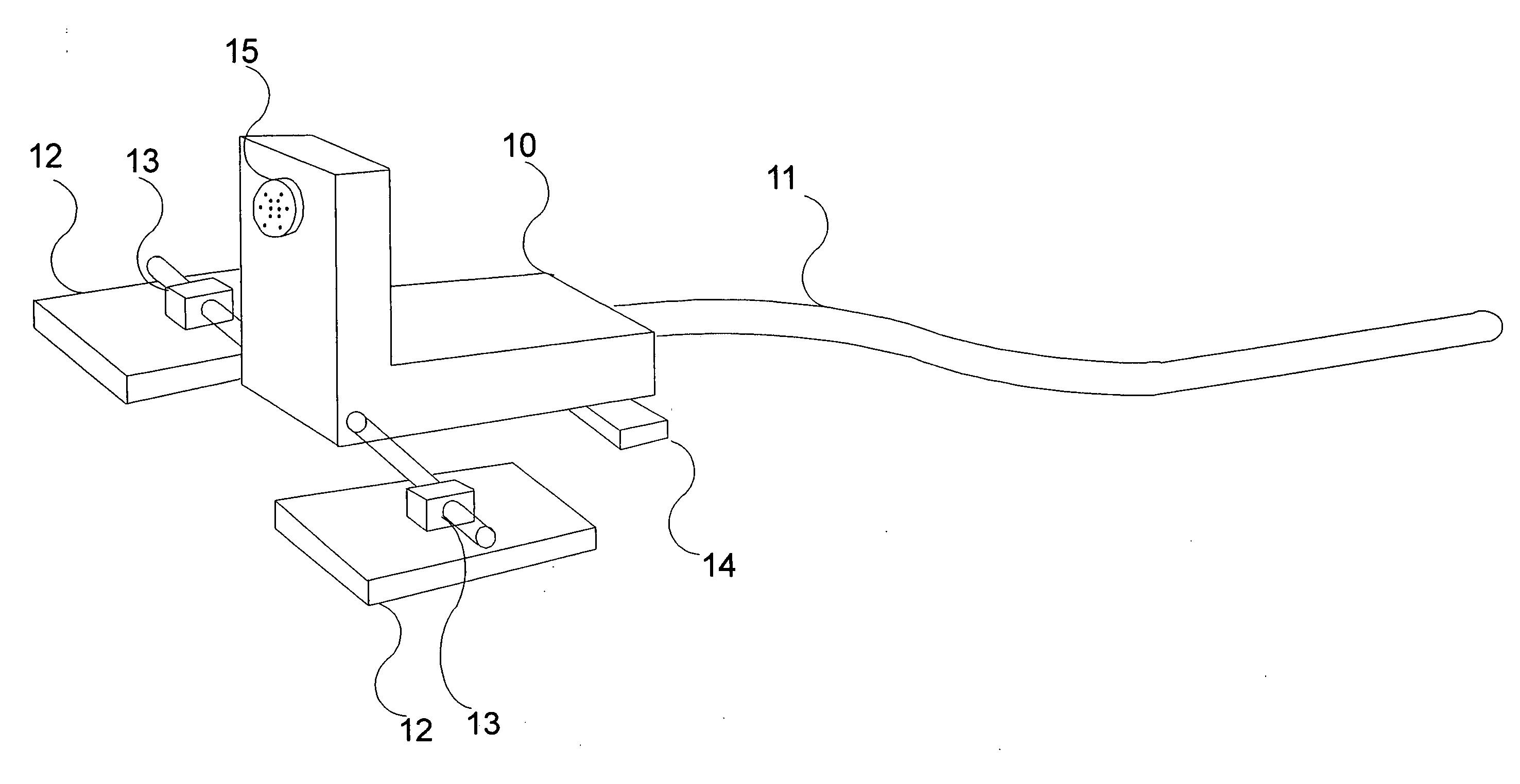
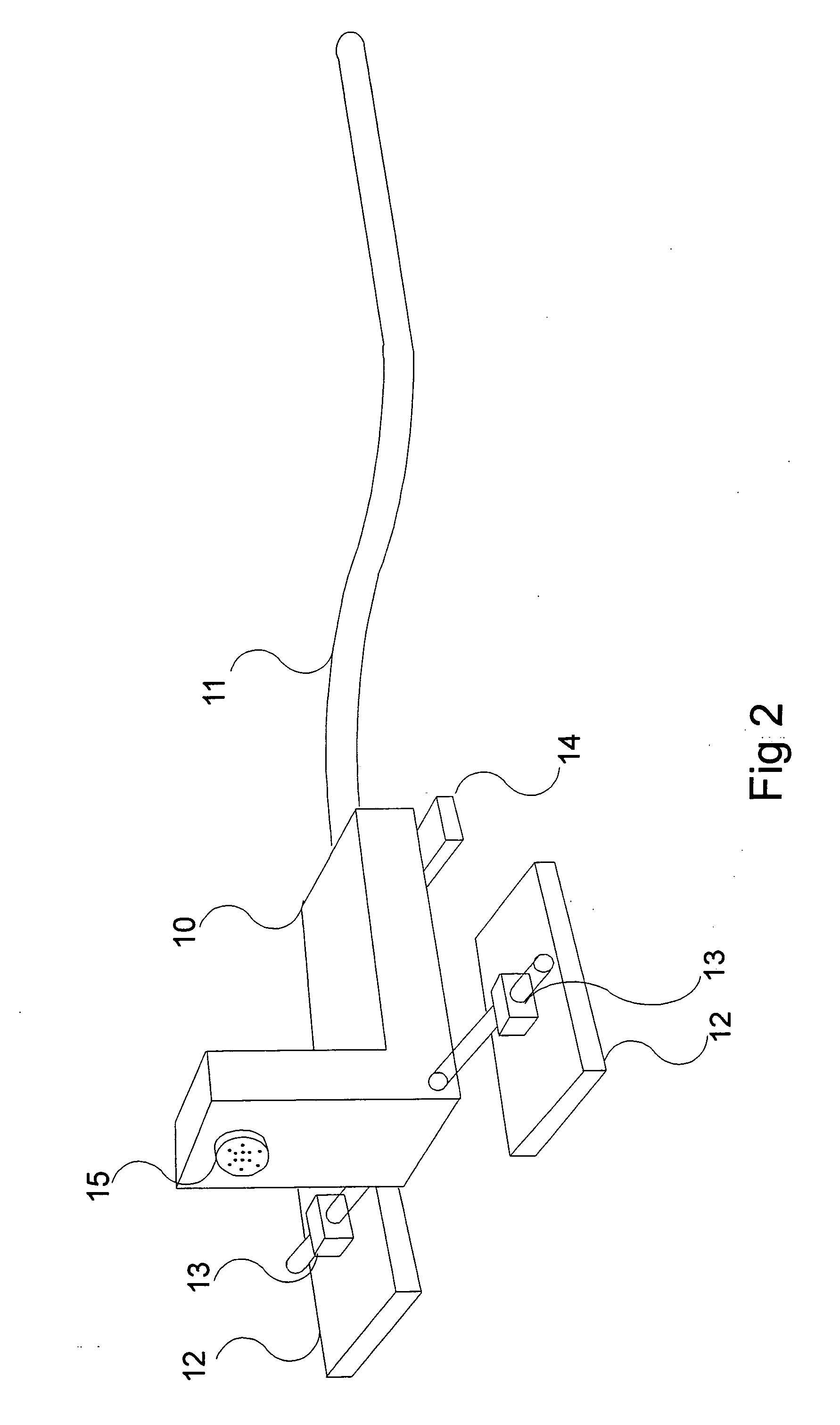
[0024]FIG. 2 is an isometric view showing a UTA 10 when installed on the sea bed by a method according to the invention. The UTA is a construction having limbs at a right-angle to each other, with one of the limbs being connected to an umbilical 11, such that the height of the umbilical 11 from the sea bed is typically less than one foot, thus obviating the need for bend restrictors. The assembly 10 is connected to two foundations provided by mudmats 12 via hinges 13 at an apex region of the construction comprising assembly 10, with an additional fixed foundation provided by a mudmat 14 at the rear of the assembly, i.e. on said one of the limbs and remote from the mudmats 12. A connector 15 on the other of the limbs provides for a link from the UTA 10.to a subsea system such as a well tree. If desired, there may be at least one further such connector on the assembly 10.

[0025]The umbilical 11 is for supplying from a surface platform or surface vessel for example, at least one of (for...


PUM


Abstract

An underwater termination assembly for use with a subsea system such as a well tree, comprises a construction having first and second limbs substantially at a right-angle to each other, which construction may be lowered having an umbilical connected to one of the limbs so that said one of the limbs sits on the bed of a body of water.

Description

FIELD OF THE INVENTION[0001]The present invention relates to umbilical termination assemblies.BACKGROUND[0002]Subsea systems such as well trees for subsea hydrocarbon extraction or injection wells, subsea manifolds and subsea distribution units are supplied with at least one of (for example) electric power, hydraulic power, control signals and chemicals via an umbilical, from a surface platform or surface vessel for example. The umbilical is terminated at the sea bed by an umbilical termination assembly (UTA). Typically, the UTA is mounted on a frame which in turn is attached to a foundation, normally a mudmat. Standard practice is to lower the mudmat to the sea bed first, whereupon it is installed at the required location so that the skirt of the mudmat penetrates the surface to provide lateral movement resistance and the top of the mudmat is level with the sea bed surface.[0003]FIGS. 1a and 1b show, diagrammatically a method of installation of a UTA. In FIG. 1a, a frame 1 has been...

Claims


Application Information

Patent Timeline
Patent Type & Authority Applications(United States)
IPC IPC(8): E21B43/013
CPCE21B19/002E21B33/0355H02G9/02H02G1/10E21B43/013H01R13/523
Inventor BARRATT, RICHARD K. O.TAYLOR, THOMAS D.
Owner GE OIL & GAS UK LTD
Why Eureka
Try Eureka