
Airplane with rear engines

a rear engine and jet engine technology, applied in the field of jet propelled aircraft, can solve the problems of heavy and structural prejudice, difficult to adapt to modern jet engine, and not optimal in aerodynamic drag, and achieve the effect of facilitating repair or service operations

Inactive Publication Date: 2010-02-18
AIRBUS OPERATIONS (SAS)
View PDF12 Cites 19 Cited by
  • Summary
  • Abstract
  • Description
  • Claims
  • Application Information

AI Technical Summary

Benefits of technology

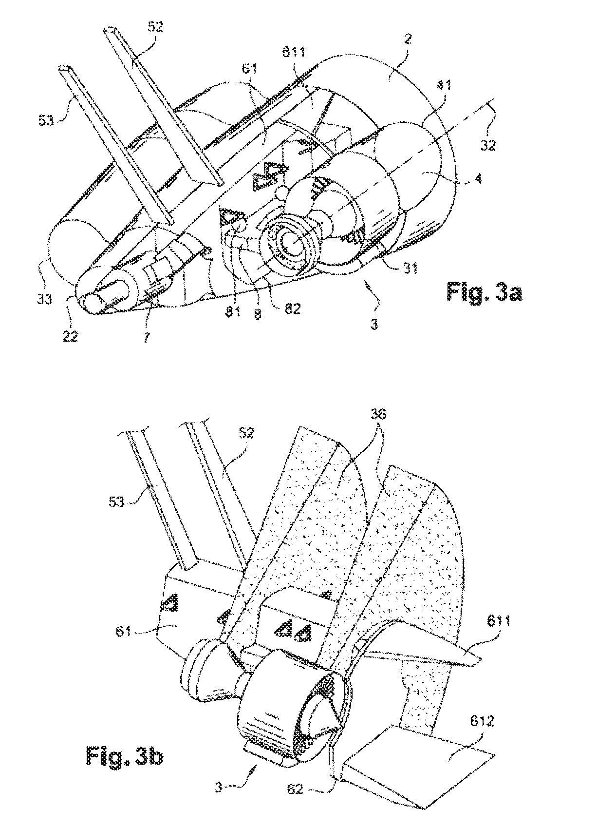
[0017]In this configuration, the semi-buried jet engines are preferably mounted to a main boom, fitted on the vertical plane of symmetry of the airplane, inside the fuselage behind a main forward frame; this unit has the advantage of a relatively simple structural design that can be made of composite materials with no major difficulty.
[0019]In one design, preferred for its structural simplicity and the absence of aerodynamic stress inside the fuselage, each half-buried jet engine is mounted to a support strut, which is mounted on the main boom.
[0026]To make repair or service operations easier, the main boom is mounted on the main forward frame so it is removable and reinforced, if need be.

Problems solved by technology

These aft engine installation configurations, while functional, have proven relatively heavy and structurally prejudicial, do not appear optimal in terms of aerodynamic drag and are hard to adapt to modern jet engines with high bypass ratios that are heavy, voluminous and require high rigidity for mounting.
Moreover, the development of non-metallic structures for fuselages, particularly structures made of composite materials, makes it more complicated to use the known solutions for aft-mounted jet engines on the fuselage.

Method used


Image

  • Airplane with rear engines
  • Airplane with rear engines
  • Airplane with rear engines

Examples


Embodiment Construction

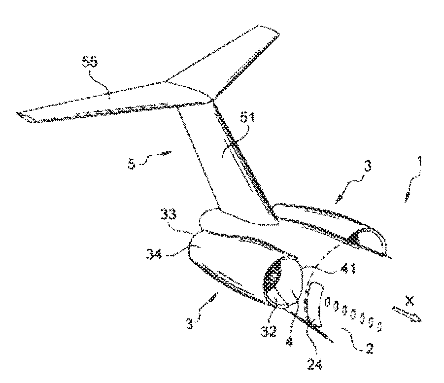
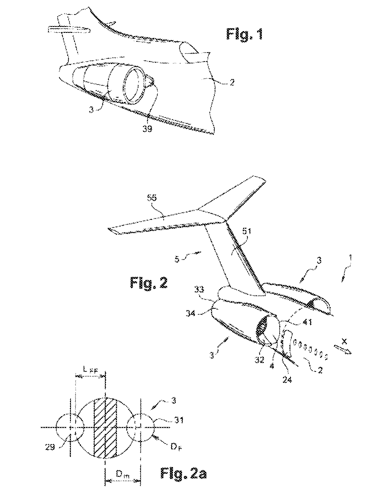
[0039]An aircraft 1, in which only the aft part is shown in FIG. 2, according to the invention, has a fuselage 2 on which are mounted two engines 3 and tail sections 5, basically a vertical rudder 51 and a horizontal tail section 55.

[0040]The description of the invention will designate “forward” and “aft” as the direction toward the front of the aircraft in the direction of movement in flight, shown by an arrow illustrating a positive axis X of an airplane mark in FIG. 2 and the direction toward the rear in the direction opposite the direction of movement in flight, respectively.

[0041]The directions when used also refer to the conventional directions in an airplane reference system. In particular, the aircraft has a general vertical plane of symmetry.

[0042]The aft jet engines 3 are mounted on the fuselage 2 in an approximately symmetrical pattern in relation to the vertical plane of symmetry of the aircraft and oriented, in the known way, so that the thrust resulting from each jet e...


PUM


Abstract

An aircraft has at least two jet-propulsion engines mounted laterally on the fuselage in a symmetrical design in the aft part of the fuselage. Each jet engine is mounted on the fuselage some distance from the vertical plane of symmetry of the aircraft, so that the jet engine, in a so-called half-buried configuration, is partly inside an envelope surface of a theoretical fuselage. The half-buried, jet engines are mounted on a main boom fitted on the vertical plane of symmetry of the aircraft, inside the fuselage in back, of a forward main frame. The tail sections are mounted on the main boom and the boom is integral with structures for transmitting forces into the forward part of the fuselage. The structure is advantageously made of fiber-reinforced composite materials.

Description

CROSS-REFERENCE TO RELATED APPLICATIONS[0001]This application claims priority to and the benefit of French Application No. 08 53591 filed on 30 May 2008, the disclosure of which is incorporated herein by reference in its entirety.BACKGROUND[0002]1. Field[0003]This invention is in the field of jet-propelled aircraft, such as civil transport planes.[0004]More specifically, the invention concerns an aircraft with at least two jet engines mounted on the aft part of the fuselage.[0005]2. Brief Description of Related Developments[0006]Modern transport planes, particularly civil passenger transport planes, use various configurations for the installation of propulsion systems.[0007]Jet engines, particularly dual-flow jet engines, are the type of engine most used today because of their performance in terms of thrust and specific consumption and their ability to cruise at high speeds, particularly around Mach 0.8, which are considered to meet current civil transport requirements.[0008]On curr...

Claims


Application Information

Patent Timeline
IPC IPC(8): B64D27/20B64D27/26
CPCB64D27/20
Inventor CAZALS, OLIVIERMANNEVILLE, ALEXIS
Owner AIRBUS OPERATIONS (SAS)
Learn More