Automated landing area detection for aircraft

a technology for aircraft and landing areas, applied in the field of automatic detection of landing areas for aircraft, can solve the problem of restricting low-visibility approaches to a relatively low number of runways

Inactive Publication Date: 2010-02-18
HONEYWELL INT INC
View PDF2 Cites 39 Cited by
  • Summary
  • Abstract
  • Description
  • Claims
  • Application Information

AI Technical Summary

Benefits of technology

[0008]This summary is provided to introduce a selection of concepts in a simplified form that are further described below in the detailed description. This summary is not intended to identify key features or essential features of the claimed subject matter, nor is it intended to be used as an aid in determining the scope of the claimed subject matter.

Problems solved by technology

Aircraft such as airplanes, helicopters, and spacecraft may be required to perform approach and landing operations under low visibility conditions, which may be caused by weather or other environmental phenomena.
Unfortunately, these requirements restrict low visibility approaches to a relatively low number of runways.

Method used


Image

  • Automated landing area detection for aircraft
  • Automated landing area detection for aircraft
  • Automated landing area detection for aircraft

Examples


Embodiment Construction

[0013]The following detailed description is merely illustrative in nature and is not intended to limit the embodiments of the subject matter or the application and uses of such embodiments. As used herein, the word “exemplary” means “serving as an example, instance, or illustration.” Any implementation described herein as exemplary is not necessarily to be construed as preferred or advantageous over other implementations. Furthermore, there is no intention to be bound by any expressed or implied theory presented in the preceding technical field, background, brief summary or the following detailed description.

[0014]Techniques and technologies may be described herein in terms of functional and / or logical block components, and with reference to symbolic representations of operations, processing tasks, and functions that may be performed by various computing components or devices. Such operations, tasks, and functions are sometimes referred to as being computer-executed, computerized, s...


PUM


Abstract

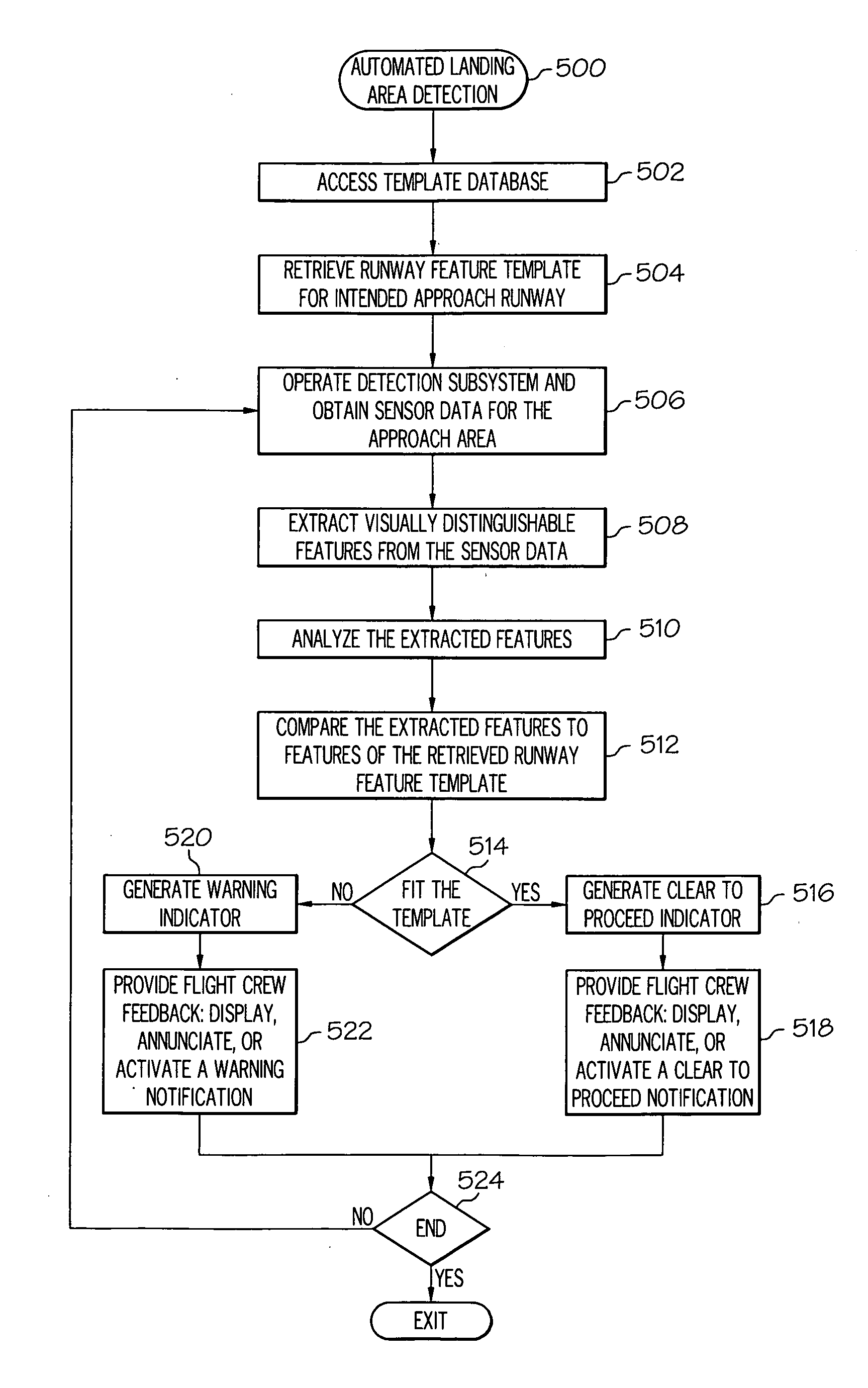
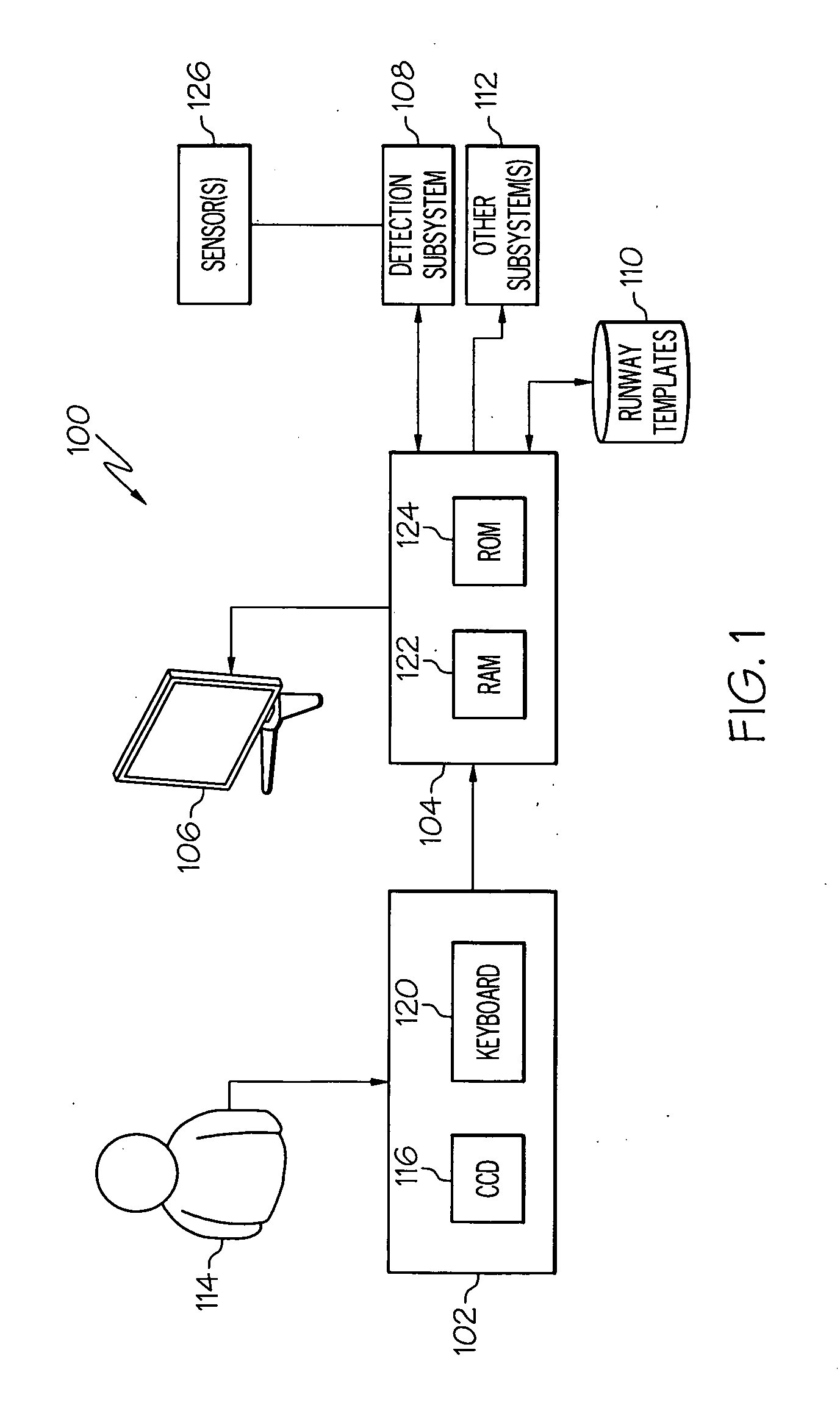
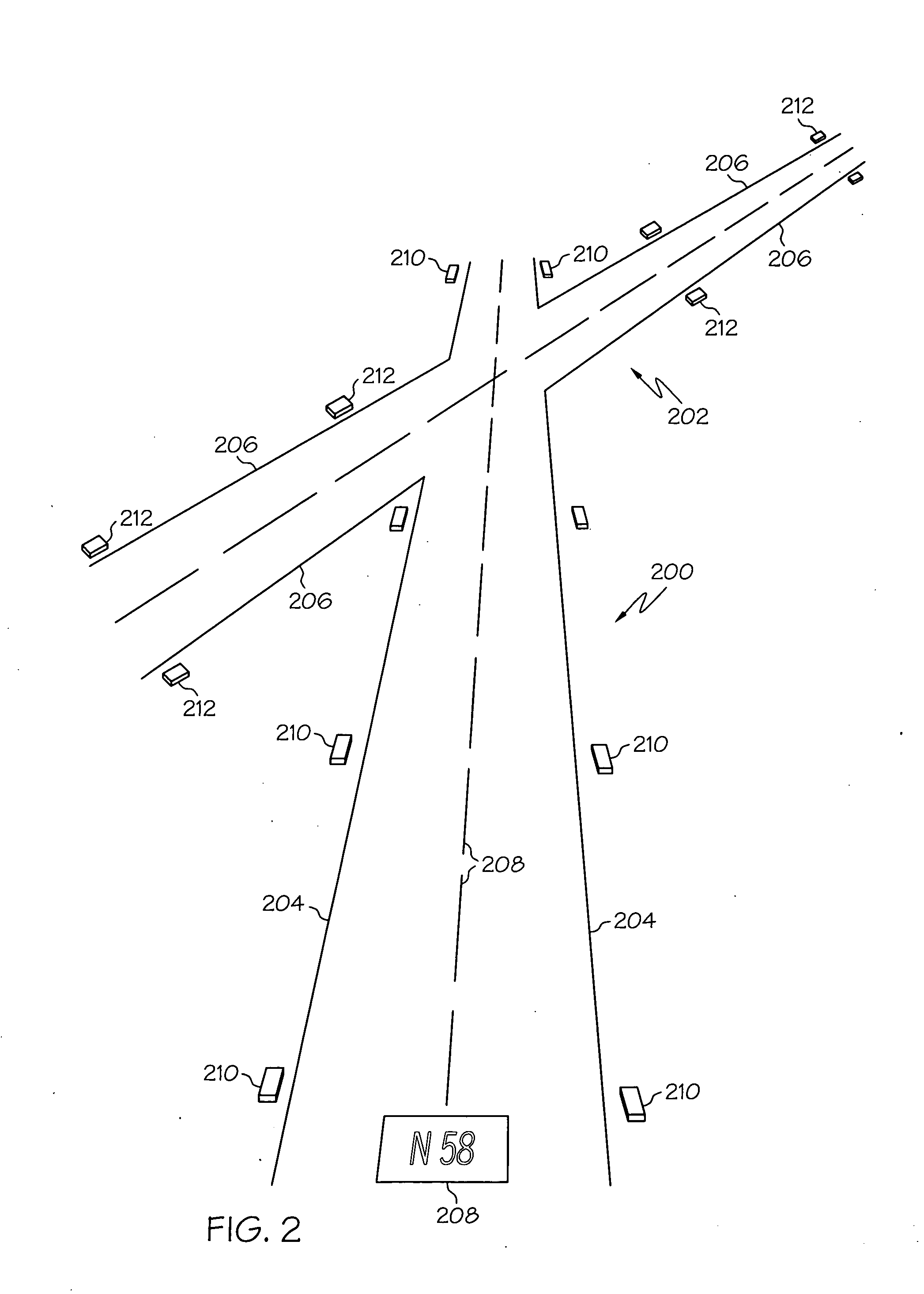
A system for detecting a landing area or runway for an aircraft includes a detection subsystem, a processor architecture, flight deck instrumentation, and a runway feature template database. The system is operated to perform an automated method for visually confirming the presence of a runway on approach. The method obtains sensor data indicative of an approach area of the aircraft, and extracts visually distinguishable features of the approach area from the sensor data. The method also accesses the runway feature template corresponding to the intended approach runway for the aircraft, fits the visually distinguishable features to the runway feature template, and provides flight crew feedback in response to the fitting step.

Description

TECHNICAL FIELD[0001]Embodiments of the subject matter described herein relate generally to avionics systems and instrumentation. More particularly, embodiments of the subject matter relate to the automated detection of the landing area for an aircraft.BACKGROUND[0002]Aircraft such as airplanes, helicopters, and spacecraft may be required to perform approach and landing operations under low visibility conditions, which may be caused by weather or other environmental phenomena. Safely landing the aircraft requires accurate information about the location of a target (e.g., runway). During an approach to a runway, the pilot must carefully control the navigation of the aircraft relative to a touchdown point. Pilots need to have a good situational awareness of the outside world through heavy fog, smoke, snow, dust, or sand, to detect runways and obstacles on runways and / or in the approach path for a safe landing. Low visibility approach and landing operations typically rely on a combinat...

Claims


Application Information

Patent Timeline
Patent Type & Authority Applications(United States)
IPC IPC(8): G01C23/00G06V20/17
CPCG01S7/412G06K9/0063G08G5/025G08G5/0086G06K9/6202G06V10/751G06V20/17
Inventor FEYEREISEN, THEA L.WYATT, IVAN S.HE, GANG
Owner HONEYWELL INT INC
Why Eureka
Try Eureka