Discharge lamp lighting device, illumination device, and liquid crystal display device

a technology of illumination device and discharge lamp, which is applied in the direction of light source, electrical apparatus, instruments, etc., can solve the problems of poor moving image display performance, deviation in luminance distribution, and non-uniform luminance of the lamp

Inactive Publication Date: 2010-02-18
MATSUSHITA ELECTRIC WORKS LTD
View PDF9 Cites 18 Cited by
  • Summary
  • Abstract
  • Description
  • Claims
  • Application Information

AI Technical Summary

Problems solved by technology

As disclosed in Patent Document 1, this burst dimming method is also applied to means for improving a liquid crystal display device to fix moving image display with indistinct outlines (called blurred moving images or edge blurs), which is incurred due to its own poorer moving image display performance than that of a CRT.
For this reason, effects of a high-impedance load and parasitic capacitance between the CCFL and a casing is not negligible, which leads to a problem that a current leakage to the casing causes a deviation in the luminance distribution, thereby making luminance of the lamp nonuniform.
Further, due to low noise, an effect on peripheral circuits such as a liquid crystal panel is also small.
However, the technique imposes large stresses on the switch SW2 due to an inrush current at the time of disconnecting a high-frequency current or at a moment when the switch SW2 is turned on, a starting voltage applied to the lamp at a moment when the switch SW2 is turned off, and the like.
Moreover, since a voltage applied to and a current flowing to the filaments are large when the switch SW2 is turned on, the lamp lif...

Method used


Image

  • Discharge lamp lighting device, illumination device, and liquid crystal display device
  • Discharge lamp lighting device, illumination device, and liquid crystal display device
  • Discharge lamp lighting device, illumination device, and liquid crystal display device

Examples


first embodiment

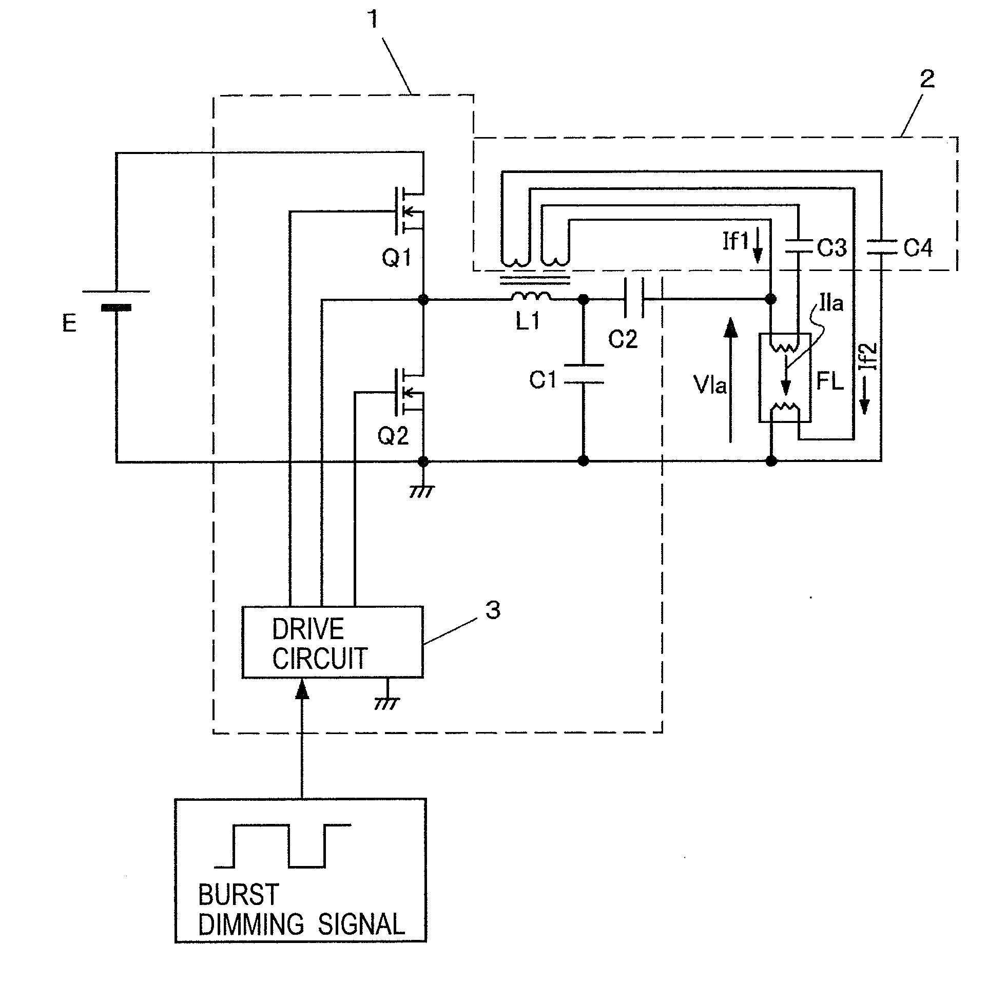
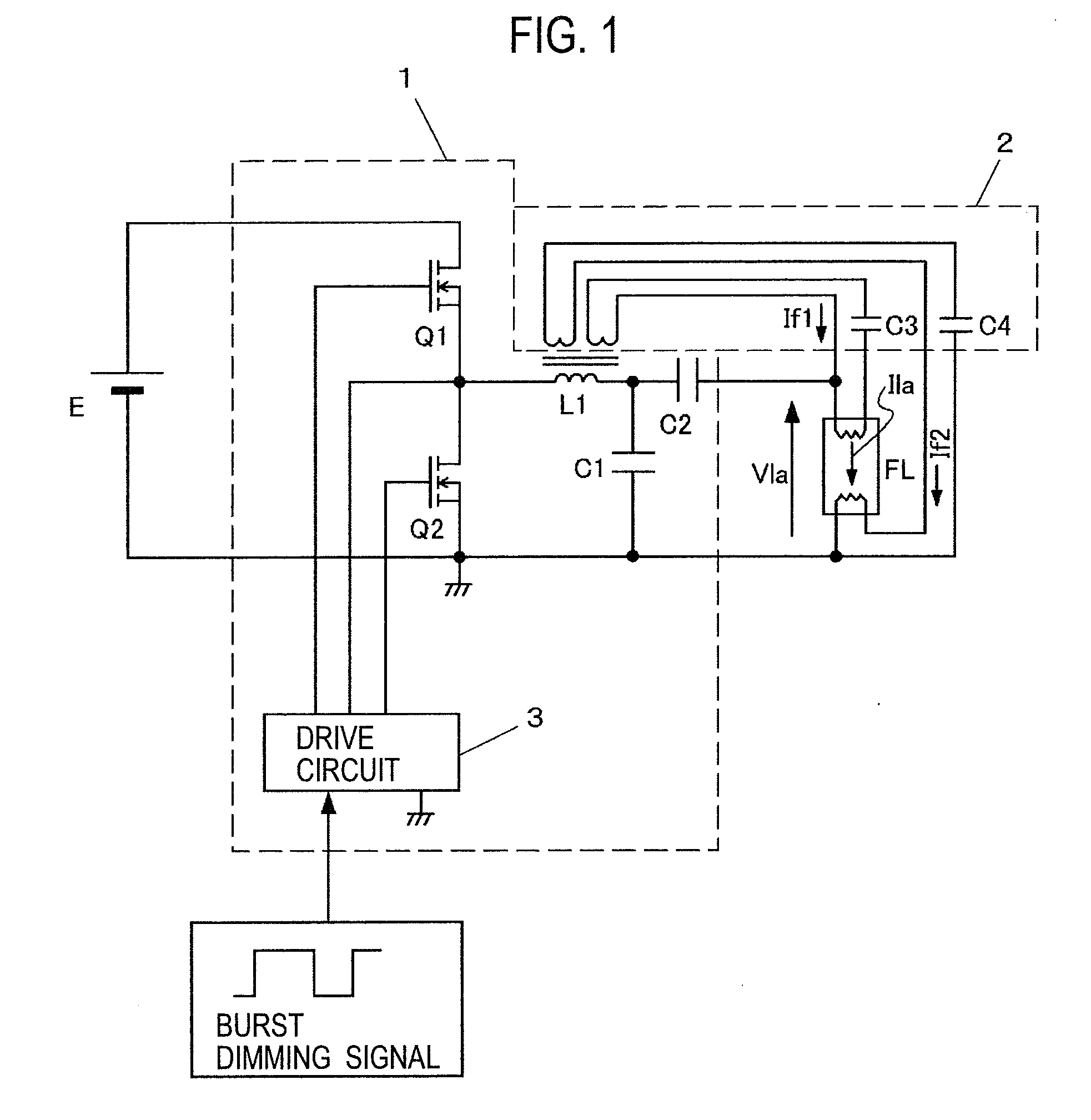
[0062]FIG. 1 is a circuit diagram showing a configuration of a discharge lamp lighting device of a first embodiment of the present invention. A DC power source E is a power source that outputs a predetermined DC voltage, which can be made of a circuit configured to rectify the whole of the waveform of a commercial AC power source, to smooth and output the voltage by using a publicly-known boost chopper circuit, for example. A series circuit including switching elements Q1 and Q2 is connected to the DC power source E. The switching elements Q1 and Q2 are made of power MOSFETs, for example, which are subjected to on-off drive alternately at a high frequency by an output from a drive circuit 3.

[0063]A series circuit including an inductor L1 and a capacitor C1 is connected between a junction of the switching elements Q1 and Q2 and a ground. A hot cathode discharge lamp FL is connected to both ends of the capacitor C1 via a DC cut capacitor C2. Together with impedance at the time of ligh...

second embodiment

[0079]FIG. 6 is a circuit diagram showing a configuration of a discharge lamp lighting device according to a second embodiment of the present invention. The discharge lamp lighting device of this embodiment has a resistor R1 provided in series with the switching element Q2 added to the discharge lamp lighting device of the first embodiment shown in FIG. 1. A source current flowing to the switching element Q2 is detected by the resistor R1, then smoothed by a low-pass filter LPF, and outputted as a detection voltage. This detection voltage is then inputted to an inverting input terminal (a negative side input terminal) of an operational amplifier OP1 to be described later via a resistor R2 and is used for feedback control.

[0080]Moreover, the discharge lamp lighting device of this embodiment has a modified configuration of a preheating circuit 2 in the discharge lamp lighting device of the first embodiment, and is provided with a preheating transformer T1 independently of the resonanc...

third embodiment

[0108]FIG. 9 is a circuit diagram of a discharge lamp lighting device according to a third embodiment of the present invention. The discharge lamp lighting device of this embodiment provides a circuit obtained by modifying the circuit of the second embodiment shown in FIG. 6, in a way that the first reference voltage V1 to be applied to the non-inverting input terminal (the positive side input terminal) of the operational amplifier OP1 is changed by a DC signal supplied from outside to make the output in the light-on period variable.

[0109]FIGS. 10(a) to 10(e) are operation waveform charts of the discharge lamp lighting device of this embodiment, which show operations in the case of setting the first reference voltage V1 smaller than that of the discharge lamp lighting device of the second embodiment. The amplitude of the lamp current Ila is smaller than that in FIG. 7. In addition, the filament current If in the light-on period is greater than that in FIG. 7.

[0110]FIG. 11 is an oper...


PUM


Abstract

A burst dimming signal to determine a ratio between an ON period and an OFF period is inputted. In the OFF period of the burst dimming signal, a lamp current Ila is stopped from flowing to a discharge lamp FL, while a lamp voltage Vla is applied to both ends of the discharge lamp FL, and preheating currents If1 and If2 are supplied to hot cathodes of the discharge lamp FL. In the ON period of the burst dimming signal, the discharge lamp FL is electrically broken down and is supplied with the lamp current Ila.

Description

TECHNICAL FIELD[0001]The present invention relates to a discharge lamp lighting device configured to perform dimming by changing a time ratio between a light-on period and a light-off period of a discharge lamp that serves as a light source, and to an illumination device and a liquid crystal display device using the same.BACKGROUND ART[0002]A liquid crystal display device includes a liquid crystal panel 22 and a backlight unit 21 located behind the panel and provided with a light source FL (see FIG. 42). In each of pixels of the liquid crystal panel 22, liquid crystal is driven by video signals, light emitted from the backlight unit 21 is transmitted therethrough, and images are displayed on the liquid crystal panel 22. In general, a cold cathode fluorescent lamp (CCFL) is often used as the light source FL of the backlight unit 21, and a discharge lamp lighting device for lighting control of the lamp is required. An example of a method of dimming the CCFL in the discharge lamp light...

Claims


Application Information

Patent Timeline
IPC IPC(8): H05B41/36G02F1/1335
CPCG02F1/133604H05B41/3921H05B41/295
Inventor MISHIMA, MASANORINARUO, MASAHIRO
Owner MATSUSHITA ELECTRIC WORKS LTD
Why Eureka
Try Eureka