Motor controller

Inactive Publication Date: 2010-02-18
YASKAWA DENKI KK
View PDF14 Cites 11 Cited by
  • Summary
  • Abstract
  • Description
  • Claims
  • Application Information

AI Technical Summary

Benefits of technology

[0032]According to the inventions of claims 1 and 2, die-casting frames in which bosses for attaching a printed circuit board and a pedestal for attaching a motor controller are integrally molded are provided on both sides of the extrusion heat sink. Thereby, it is possible to reduce the number of parts, and it is possible to reduce the man-hours of assembling, thereby reducing costs.
[0033]According to the invention of claim 3, screws are not used for attachment of the extrusion heat sink and the die-casting frames. Therefore, it is possible to reduce the number of parts, and it is possible to reduce the man-hours of assembling, thereby reducing costs.
[0034]According to the inventions of claims 4 and 5, the plastic case and the d

Problems solved by technology

In the die-casting heat sink, it is difficult to make the pitch of fins small due to limitations in manufacture.
Therefore, fins with a narrow pitch of 8 mm or less cannot be molded.
Therefore, heat-radiating area cannot b

Method used


Image

  • Motor controller
  • Motor controller
  • Motor controller

Examples


Example

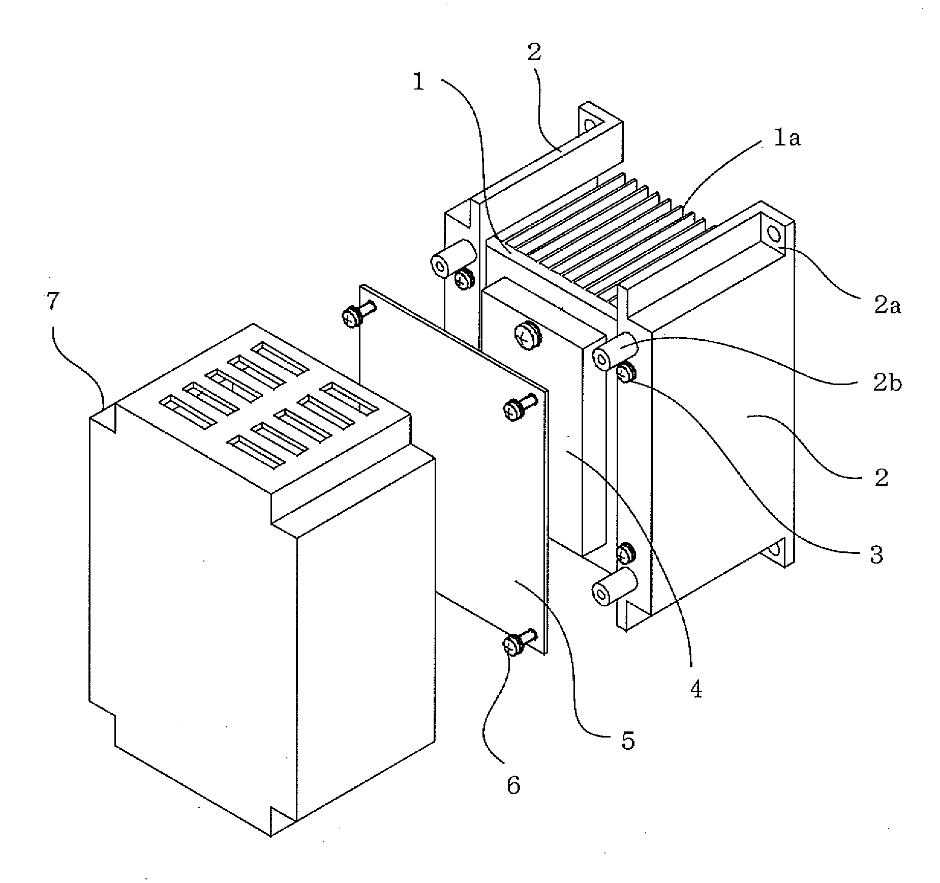
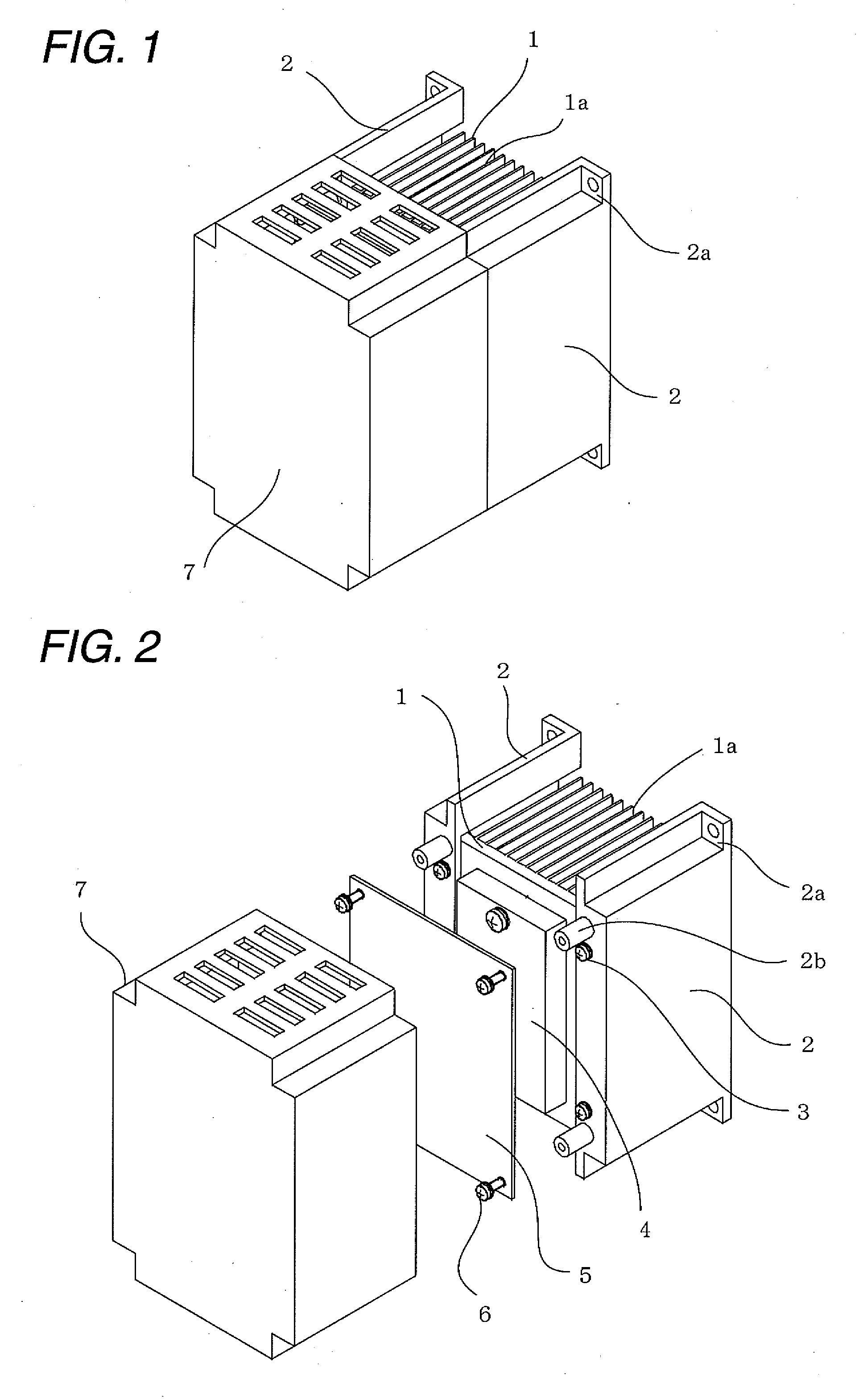
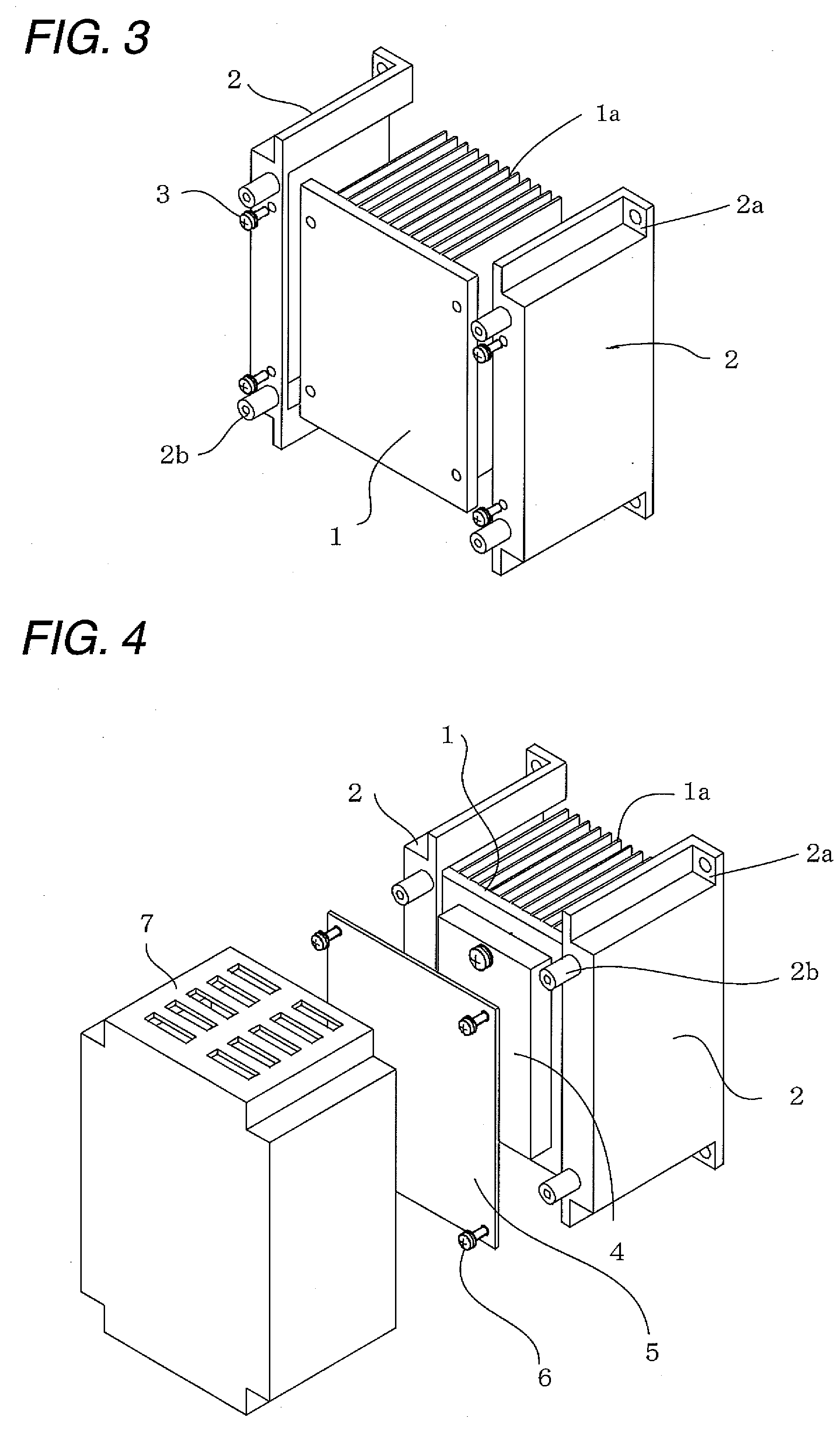
[0062]FIG. 1 is a perspective view of a motor controller showing a first embodiment of the invention. FIG. 2 is an exploded perspective view of the motor controller in FIG. 1. FIG. 3 is a detail view showing an attachment structure of a heat sink and die-casting frames in FIG. 1.

[0063]In FIGS. 1 to 3, an extrusion heat sink 1 is formed with fins 1a, and a surface opposite to the fins is a flat surface. The fins 1a are integrally molded by extrusion, or are attached by caulking. Die-casting frames 2 are fixed to both ends of the extrusion heat sink 1 with screws 3. A pedestal 2a for attaching a motor controller to a control panel and bosses 2b for attaching a printed circuit board are integrally molded with each die-casting frame 2. A power semiconductor module 4 is mounted on a flat surface portion of the extrusion heat sink 1. The heat of the power semiconductor module 4 is transferred to and radiated to the extrusion heat sink 1. A printed circuit board 5 is fixed to the bosses 2a...

Example

[0065]FIG. 4 is an exploded perspective view showing a motor controller of a second embodiment.

[0066]In FIG. 4, an extrusion heat sink 1 is formed with fins 1a, and a surface opposite to the fins 1a is a flat surface. The fins 1a are integrally molded by extrusion, or are attached by caulking. Die-casting frames 2 are fixed to both ends of the extrusion heat sink 1 by press fitting or caulking. A pedestal 2a for attaching a motor controller to a control panel and bosses 2b for attaching a printed circuit board are integrally molded with each die-casting frame 2. A power semiconductor module 4 is mounted on a flat surface portion of the extrusion heat sink 1. The heat of the power semiconductor module 4 is transferred to and radiated to the extrusion heat sink 1. A printed circuit board 5 is fixed to the bosses 2a for attaching a printed circuit board, which are integrally molded with the die-casting frames 2, with screws 6, and are electrically connected to the power semiconductor m...

Example

[0068]FIG. 5 is an exploded perspective view showing a motor controller of a third embodiment.

[0069]In FIG. 5, an extrusion heat sink 1 is formed with fins 1a, and a surface opposite to the fins is a flat surface. The fins 1a are integrally molded by extrusion, or are attached by caulking. Die-casting frames 2 are fixed to both ends of the extrusion heat sink 1 by press fitting or caulking. A pedestal 2a for attaching a motor controller to a control panel, bosses 2b for attaching a printed circuit board, and ratches 2c for attaching a plastic case are integrally molded with each die-casting frame 2. A power semiconductor module 4 is mounted on a flat surface portion of the extrusion heat sink 1. The heat of the power semiconductor module 4 is transferred to and radiated to the extrusion heat sink 1. A printed circuit board 5 is fixed to the bosses 2a for attaching a printed circuit board, which are integrally molded with the die-casting frames 2, with screws 6, and are electrically ...


PUM


Abstract

A motor controller which is inexpensive and has high cooling performance by using an extrusion heat sink (1), reducing the number of parts, and reducing the man-hours of assembling is provided. In a motor controller including an extrusion heat sink (1), and a power semiconductor module (4) including a plurality of external electrode terminals which closely contact the extrusion heat sink (1), and a printed circuit board having the plurality of external electrode terminals connected thereto, die-casting frames (2) in which a pedestal (2a) for attaching a motor controller and bosses (2b) for attaching a printed circuit board are molded are provided at both ends of the extrusion heat sink (1).

Description

TECHNICAL FIELD[0001]The present invention relates to a motor controller, such as an inverter device or a servo amplifier, which operates mainly by a high-voltage power supply, and particularly, to a heat sink for enhancing the radiating effect of a motor controller.RELATED ART[0002]A conventional motor controller, for example, an inverter device is mounted with a plurality of power semiconductor modules that are heat-generating parts, and is mounted with a heat sink for cooling the plurality of power semiconductor modules (for example, refer to Patent Document 1). The configuration of a conventional motor controller, for example, an inverter device, is shown in FIGS. 7 to 9.[0003]FIG. 7 is an exploded perspective view showing a conventional motor controller using a die-casting heat sink.[0004]In FIG. 7, a pedestal 101a for attaching a motor controller to a control panel, bosses 102b for attaching a printed circuit board (PCB), and ratches 101c for attaching a plastic case are integ...

Claims


Application Information

Patent Timeline
IPC IPC(8): H05K7/20H01L23/40H02K11/30H02M7/48
CPCH05K7/209H02K11/33H02M7/003
Inventor NUKI, KOJI
Owner YASKAWA DENKI KK
Why Eureka
Try Eureka