
Folded light path LED array collimation optic

Active Publication Date: 2010-02-18
LIGHTING SCI GROUP
View PDF13 Cites 35 Cited by
  • Summary
  • Abstract
  • Description
  • Claims
  • Application Information

AI Technical Summary

Benefits of technology

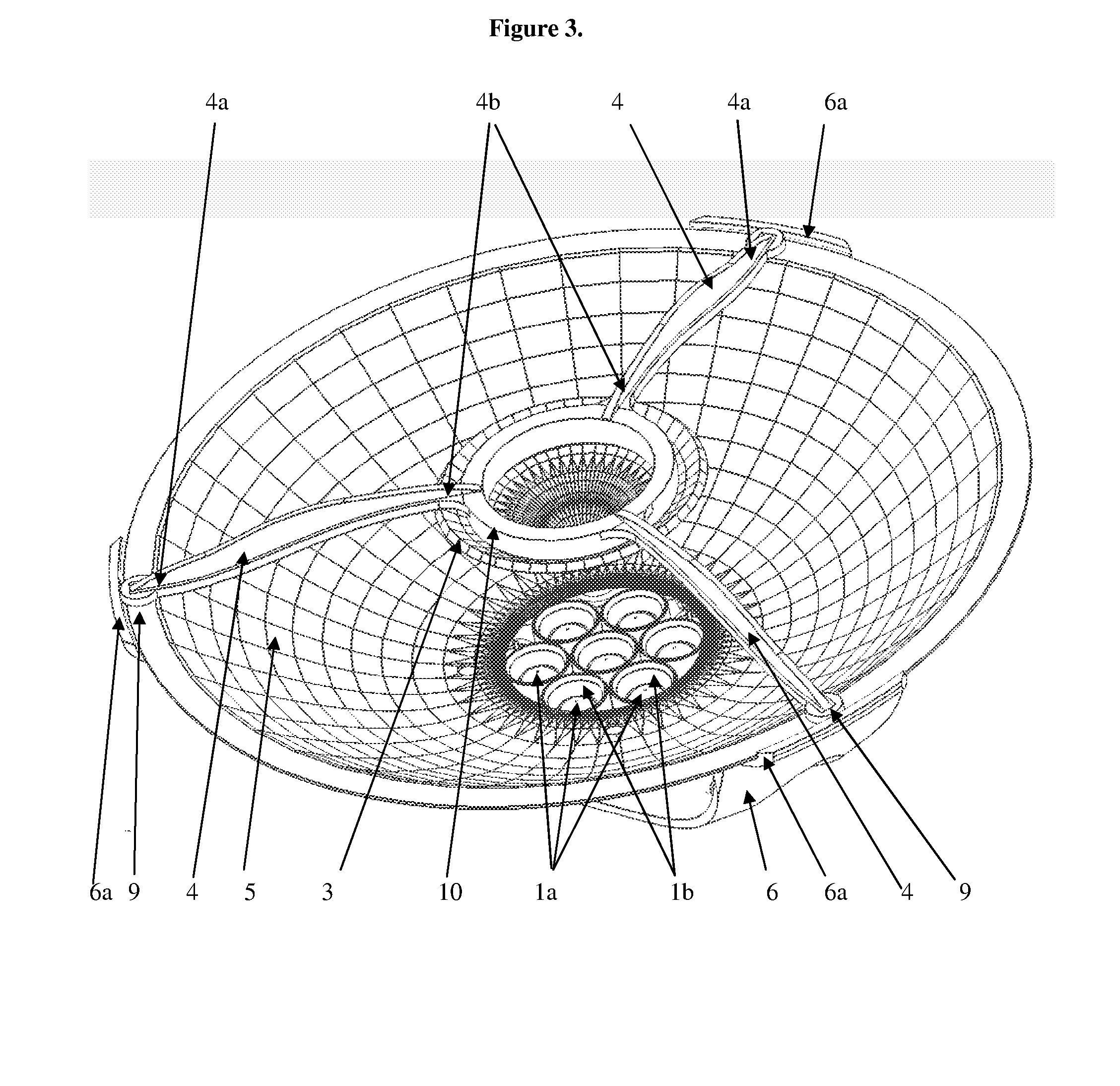
[0008]According to the present invention, an optical assembly produces a narrow beam by replacing a single tall reflector with a compact optical system including two revolved spline reflectors, e.g., ≦2″ tall and ≦5″ wide. Micro-facets on the reflectors improve the uniformity of the beam with a minimal degradation in intensity dispersion. Light emitted by the LEDs passes through an optical assembly including the optical features of a primary reflector and a secondary reflector, the reflectors having predetermined shapes which cooperatively match in order to produce a light beam having a desired amount of collimation.

Problems solved by technology

Such light engines typically include multiple emitters and cavities to produce a light beam having an acceptable intensity, however this increases the apparent source size to be much larger than the apparent source size from a single emitter light engine, thereby making it more difficult to collimate the light into a beam having a low level of intensity dispersion.
Conventional collimation solutions which are tall (e.g., ≧5″) or wide (e.g., ≧6″) are too costly to manufacture, ship, and install when the light source itself is already two to three times the cost of energy-inefficient incandescent and halogen sources that it replaces.

Method used


Image

  • Folded light path LED array collimation optic
  • Folded light path LED array collimation optic
  • Folded light path LED array collimation optic

Examples


Embodiment Construction

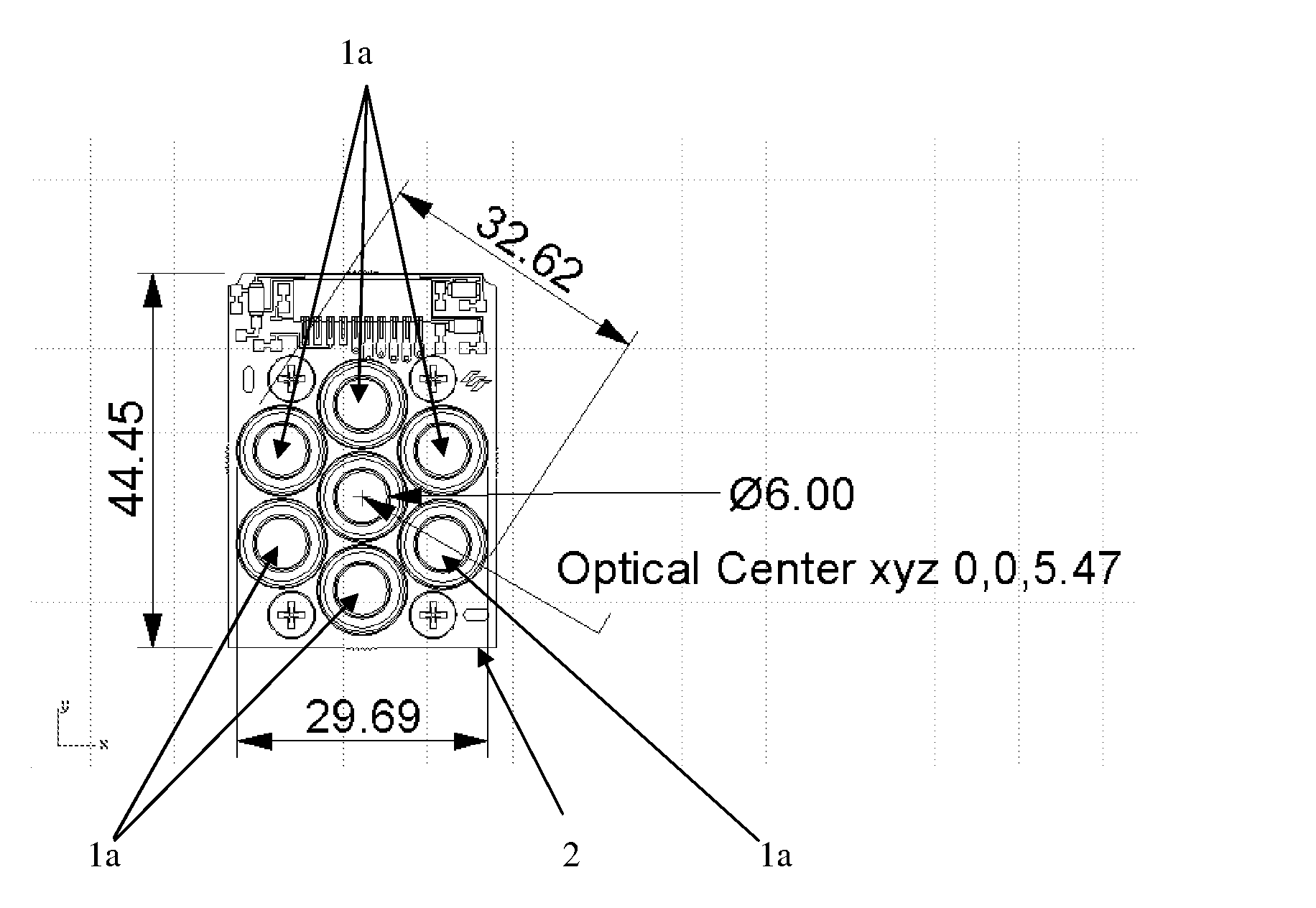
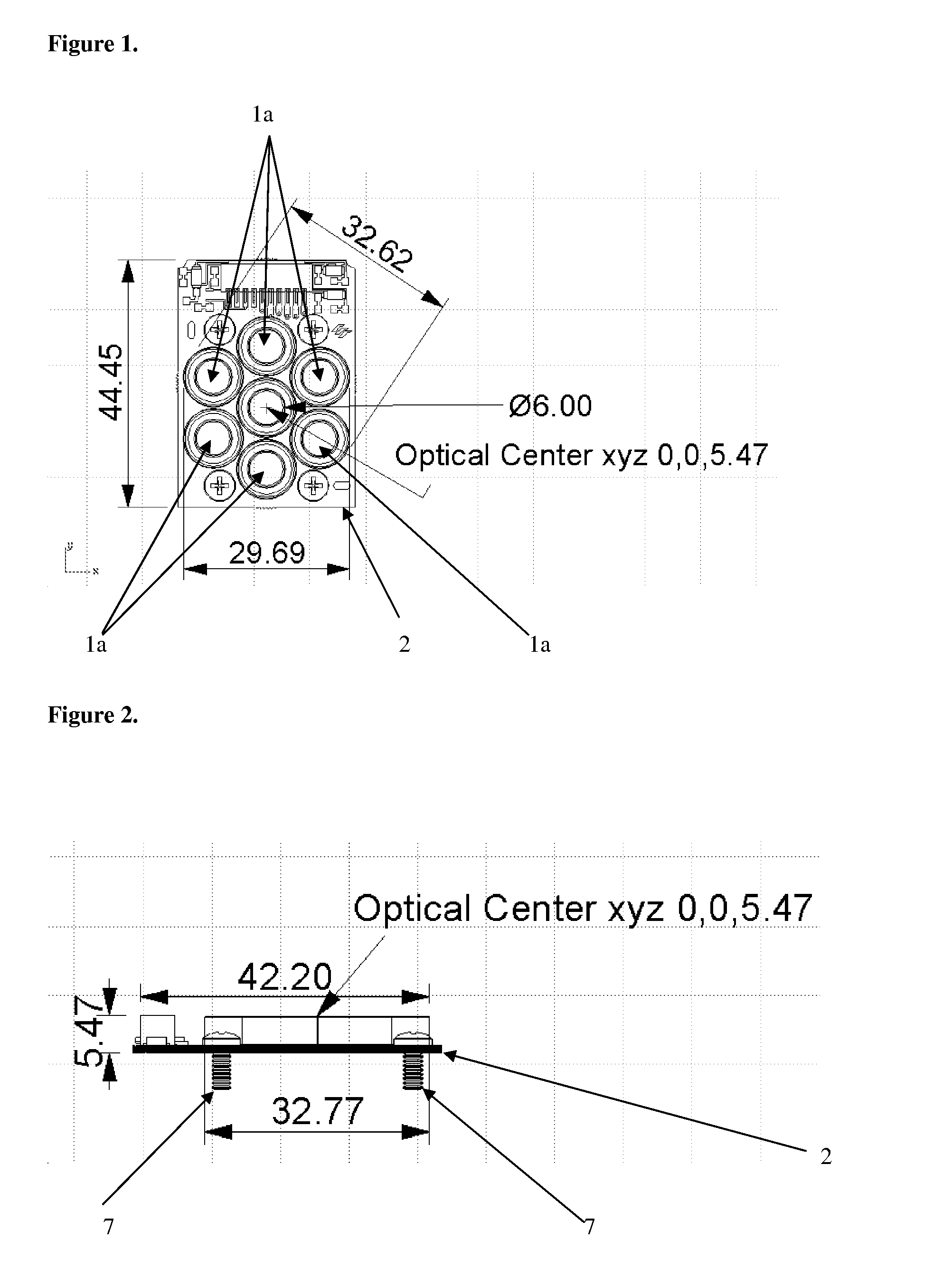
[0037]FIG. 1 is a top view of LED placement locations within a plurality of light engine cavities in accordance with an embodiment of the present invention. Preferably, the cavities have a reflective inner surface, and each cavity has a light extraction lens encapsulating the LED. The individual LEDs 1a may be a blue excitation emitter with wavelength 440-495 nm, a direct emission red, orange, or amber excitation emitter with wavelength range 575-680 nm, or a direct emission green wavelength excitation emitter having a range 495 nm-575 nm. White light may be produced by exciting a yellow phosphor with light from blue LEDs. The LEDs are typically mounted on a substrate 2 which provides electrical connections, thermal dissipation, and mechanical support. Placement and quantity of LEDs 1a may vary from the placement shown in FIG. 1. Typical dimensions in millimeters of the light engine are shown in FIG. 1. For instance, the light engine of FIG. 1 is shown having an optical axis coincid...


PUM


Abstract

Embodiments of the present invention relate to a compact optical assembly which improves collimation of light produced by multiple LED light sources in a light engine. A shaped primary reflector located over the light engine reflects the light toward a larger shaped secondary reflector. The shapes of the reflectors are selected to cooperatively produce a highly collimated light beam. Color mixing may be improved by providing a plurality of facets on the reflective surfaces of at least one of the primary reflector or the secondary reflector.

Description

[0001]This application claims priority from U.S. Provisional Patent Application No. 60 / 885,224, the entire content of which is hereby incorporated by reference in its entirety.[0002]Numerous references including various publications may be cited and discussed in the description of this invention. The citation and / or discussion of such references is provided merely to clarify the description of the present invention and is not an admission that any such reference is “prior art” to the present invention. All references cited and discussed in this specification are incorporated herein by reference in their entirety and to the same extent as if each reference was individually incorporated by reference.FIELD OF THE INVENTION[0003]This invention relates to optical devices. More specifically, embodiments of the present invention relate to a folded optical system with compact free form reflectors, which collimate a multi-cavity LED light engine to a narrow beam.BACKGROUND OF THE INVENTION[0...

Claims


Application Information

Patent Timeline
IPC IPC(8): F21V7/10G02B17/06
CPCF21V7/0008F21V7/0025F21Y2101/02F21V7/09F21W2131/406F21V7/04F21Y2115/10
Inventor BAILEY, EDWARD
Owner LIGHTING SCI GROUP
Learn More