
Indoor wireless positioning system and method

Inactive Publication Date: 2010-02-18
ELECTRONICS & TELECOMM RES INST
View PDF8 Cites 117 Cited by
  • Summary
  • Abstract
  • Description
  • Claims
  • Application Information

AI Technical Summary

Benefits of technology

[0018]As described above, there is provided to the user an effective entire system and method for indoor wireless positioning capable of overcoming a limitation imposed by an indoor environment having built-in access points using indoor wireless communication devices using WLAN, Bluetooth, and UWB, providing the indoor environment-based fingerprint database creation method in order to provide reliable positioning information to a user, providing a database-based terminal position estimating method, and providing a terminal / server-based position estimating method.
[0019]In addition, a simulation error of the software tool can be corrected using the hardware tool, so that it is possible to accurately provide an indoor wireless positioning result.
[0020]The present invention is not limited to the aforementioned embodiments, but may be modified for use in applications such as indoor positioning based on the wireless communication using the WLAN and UWB or outdoor wireless positioning by those skilled in the art.

Problems solved by technology

However, in some cases, such as while indoors, in a tunnel, in an underground parking lot, or in the center of the city, the GPS receiver cannot completely or can only partially receive a GPS satellite signal.
Therefore, there is a problem in that the GPS cannot continuously provide position information.
However, a wireless communication access point (AP) for the indoor positioning and a modem are not in time synchronization with each other, so that the ToA cannot be used.
In addition, in the WLAN, the APs are not in synchronization with each other, so that a time difference of arrival (TDOA) cannot be used either.
However, there are problems in that it takes much time to construct the database and it is difficult to accurately construct data.

Method used


Image

  • Indoor wireless positioning system and method
  • Indoor wireless positioning system and method
  • Indoor wireless positioning system and method

Examples


Embodiment Construction

[0041]Hereinafter, exemplary embodiments of the present invention will be described in detail with reference to the attached drawings.

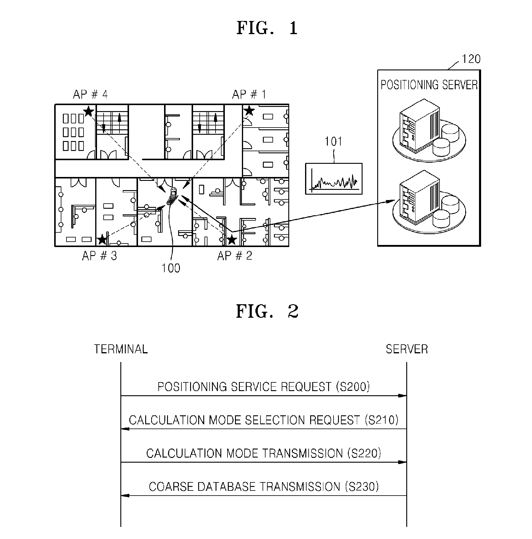
[0042]FIG. 1 is a view showing a structure of a terminal-based indoor wireless positioning system according to an embodiment of the present invention. Referring to FIG. 1, the indoor wireless positioning system includes a terminal 100, a positioning server 120, and wireless communication access points.

[0043]In a terminal-based position calculation mode, a fingerprint coarse database 101 transmitted from the server 120 to the terminal 100 is included. Here, the coarse database 101 is a fingerprint database having a small capacity constructed by setting fingerprint grids to be larger when a database for indoor positioning is created.

[0044]The positioning server 120 transmits the fingerprint coarse database 101 stored in advance to the terminal 100. The terminal 100 stores the database 101 transmitted from the positioning server 120 in a memory.

[0045]The...


PUM


Abstract

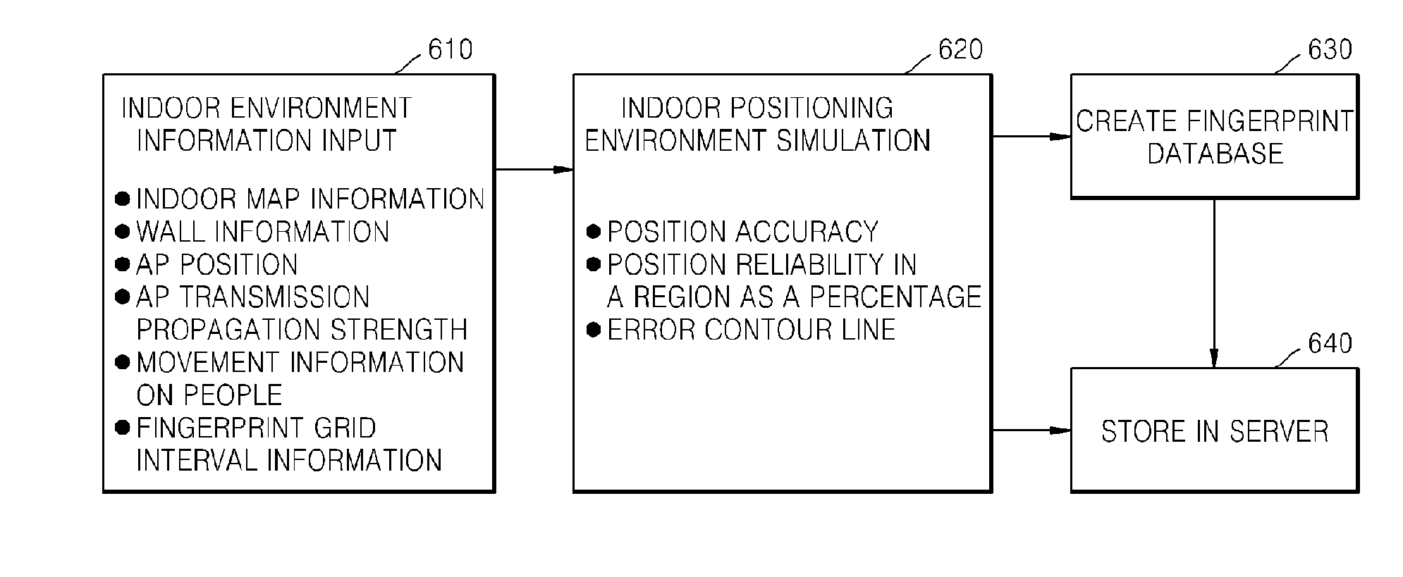
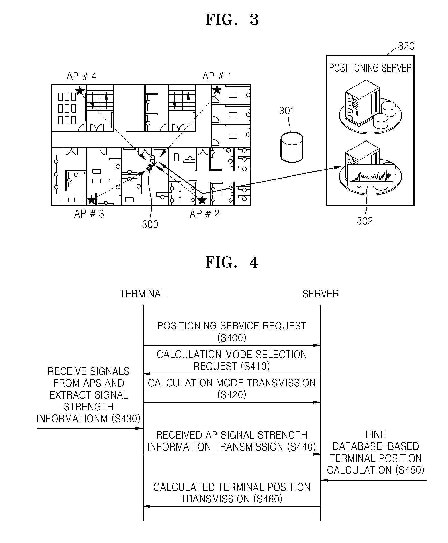
Provided is an indoor wireless positioning system and method including: a signal receiving unit receiving first signals from wireless communication access points and measuring strengths of the received first signals and a position estimating unit estimating a current position by comparing the strengths of the first signals measured by the signal receiving unit with a table recording strengths of second signals predicted by a simulation for indoor space the system is currently positioned. Accordingly, it is possible to rapidly and accurately create a fingerprint database and calculate position information on the terminal in the terminal or the server on the basis of the database information.

Description

TECHNICAL FIELD[0001]The present invention relates to an indoor wireless positioning system and method, and more particularly, to a terminal-based positioning method and a server-based positioning method of providing a position of a terminal capable of creating a fingerprint database for indoor positioning using a wireless communication system such as a wireless local area network (WLAN), bluetooth, or an ultra-wideband (UWB) and using a software-based simulator.BACKGROUND ART[0002]In general, due to the development of satellite-based global positioning system (GPS) receivers, GPS receivers have been used as positioning sensors in commercial vehicle navigation systems. For example, using position information on a vehicle acquired by the GPS receiver, a location based service (LBS) providing, for example, traffic information or a location-based information service is provided.[0003]However, in some cases, such as while indoors, in a tunnel, in an underground parking lot, or in the ce...

Claims


Application Information

Patent Timeline
IPC IPC(8): H04L12/28H04L12/26G06F11/07G01S5/02
CPCG01S5/0252G01S1/68G01S5/02528G01S5/02521G01S1/028H04W64/00
Inventor CHO, SEONG-YUNKIMCHO, YOUNG-SUCHOI, WAN-SIKPARK, JONG-HYUN
Owner ELECTRONICS & TELECOMM RES INST
Learn More