Strapping System and Method to Reinforce Framed Structures

a technology of framed structures and reinforced beams, applied in the direction of buildings, construction, building repairs, etc., can solve the problems of interiors and structures often damaged, subject to significant damage, and most structures have relatively poor inherent resistan

Inactive Publication Date: 2010-02-25
FANNON DAVID J +1
View PDF17 Cites 7 Cited by
  • Summary
  • Abstract
  • Description
  • Claims
  • Application Information

AI Technical Summary

Benefits of technology

[0013]It is a further object of the invention to provide a structure stabilizing method that presents a simple approach to designing and installing a network of interconnected, tensioned straps to accommodate a wide range of building types, sizes and roofing configurations.

Problems solved by technology

Without some type of reinforcement means, most structures have relatively poor inherent resistance and are subject to significant damage from such events.
Interiors and structures are often damaged from the separation of roof decking from framing members.
Wood, the most common framed structure building material, has relatively poor tensile strength.
None of the existing concepts or devices addresses the overall structure and roof decking by connecting all of the structural and decking components with one network system that allows the entire structure and the individual components to act together to counter external forces.

Method used


Image

  • Strapping System and Method to Reinforce Framed Structures
  • Strapping System and Method to Reinforce Framed Structures
  • Strapping System and Method to Reinforce Framed Structures

Examples


Embodiment Construction

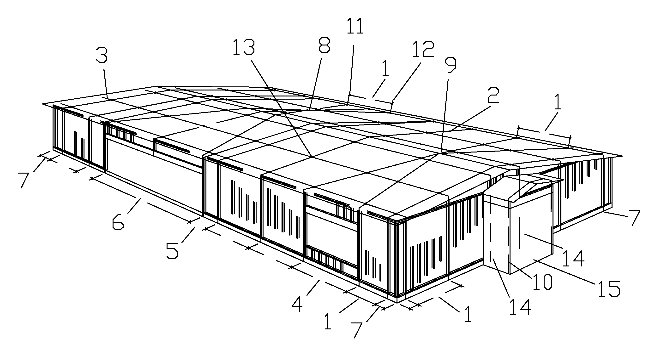
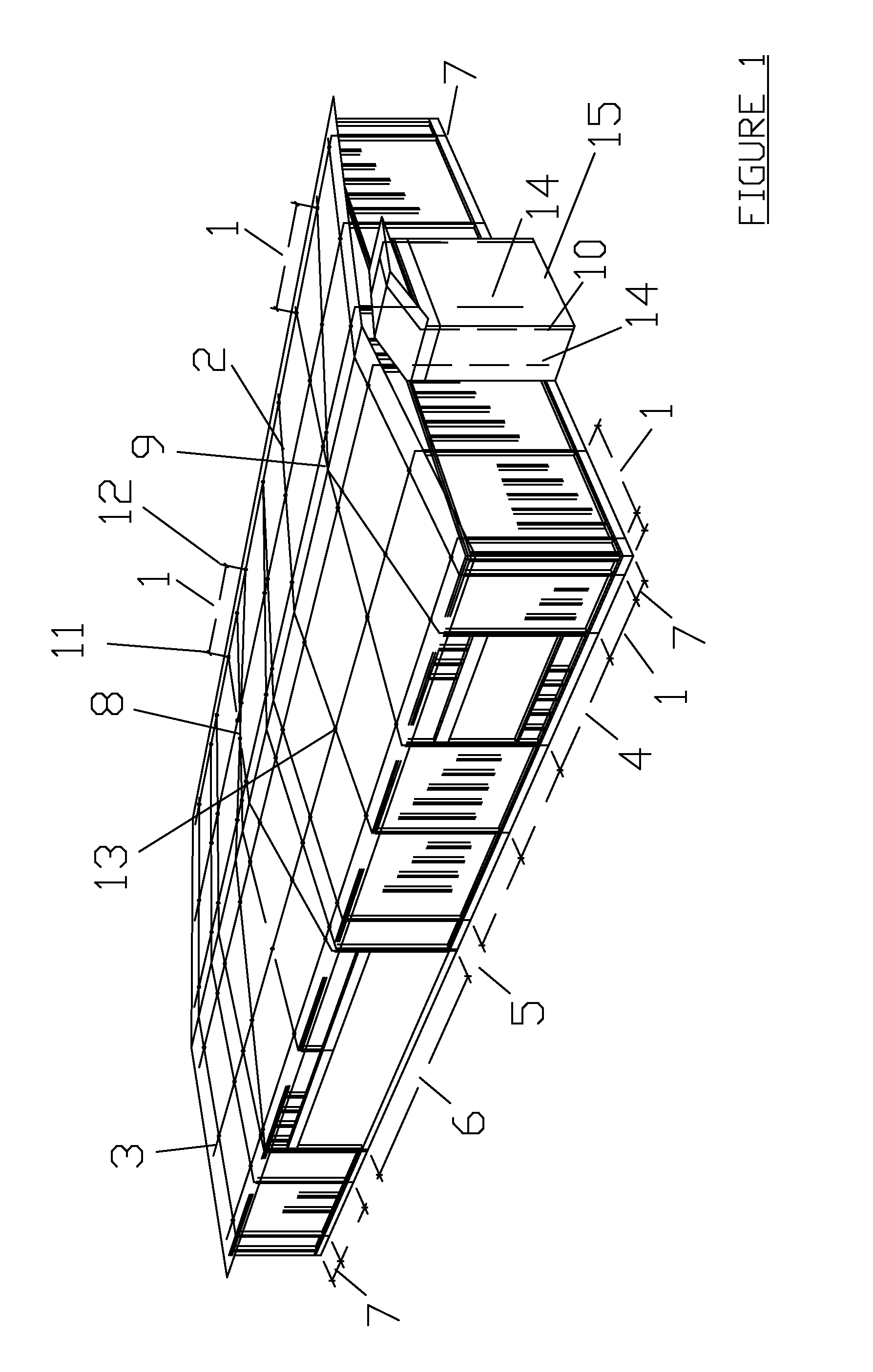
[0024]In reference to FIG. 1, a standard 4-sided structure with an angled roof and eave is shown with the strapping system of the present invention in place. Item 1 represents the standard strap spacing determined by the installer based upon the degree of resistance desired or required by local Building Codes. The inventors have determined that 3 to 10 feet spacing will be adequate for most Code requirements and external forces to be expected in the United States. The shorter the standard spacing, more straps will be present for a given building dimension and greater structural resistance will result. For example, 3-feet spacing may be required to protect a structure directly on the coast, which may be subject to the highest wind force of a hurricane. However, greater standard spacing may be desired further inland as hurricane winds tend to decrease once the storm moves further over land.

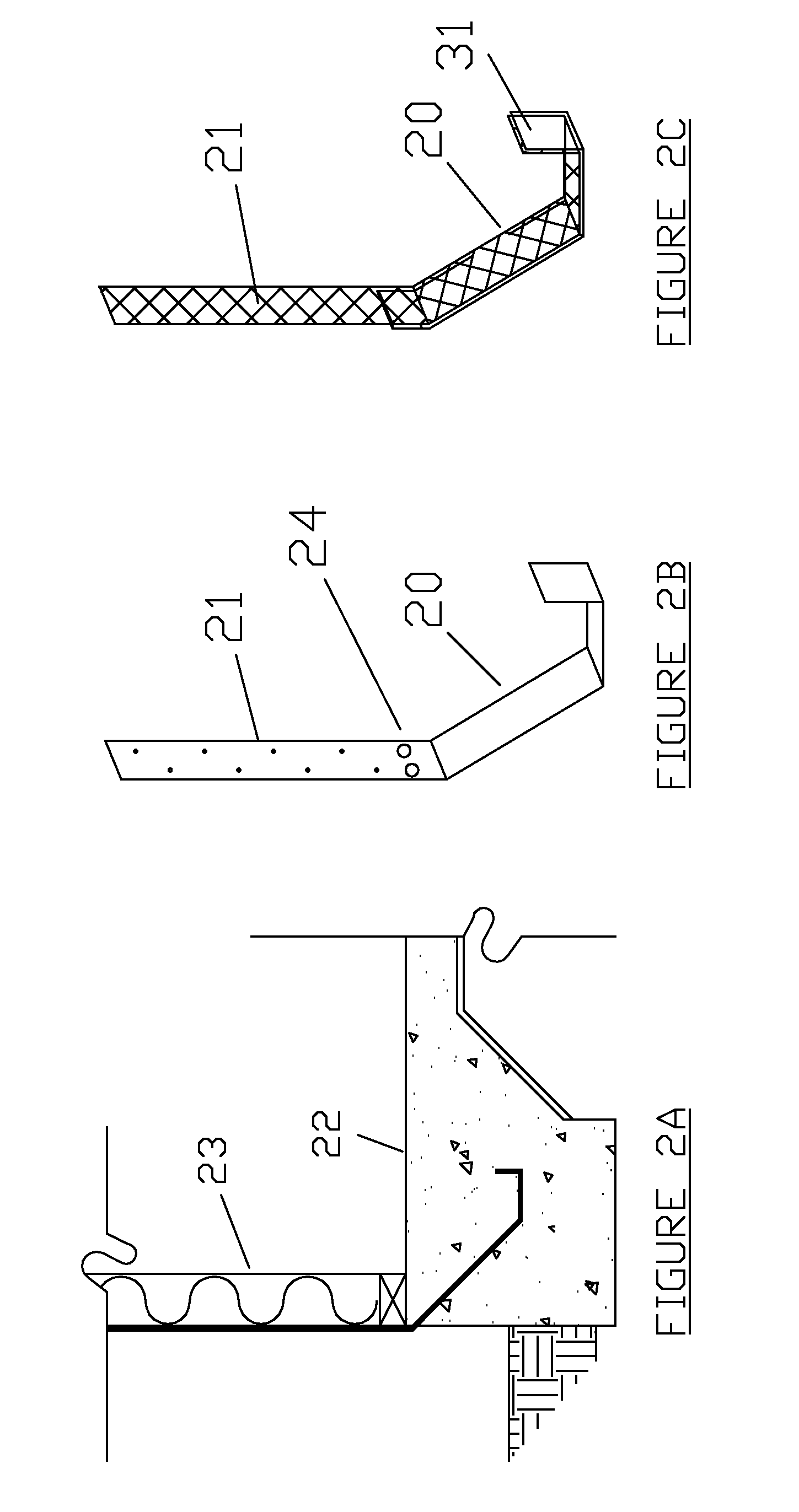
[0025]The strapping system of this typical structure is designed by first locating the end-wall ...


PUM


Abstract

A network of straps is placed over a framed structure and roof decking and secured to the foundation. A tensional force is applied to the straps. The tensioned straps are then secured at strap crossing points, the roof decking, roof structural members and wall structural members. The method also provides special treatment for straps crossing apex ridges or valleys of the structure's roof. Additional framing blocks are included under the roof decking to accommodate fastening the straps to the primary structural members. The runner straps pass through slits cut into roof decking near where the sidewalls attach to the roof joists and rafters. An added framing member or supporting structural device is also installed above the top plate of the stud wall to support the roof decking as tension is applied to the straps. The method calls for determining standard strap spacing based on the design resistance required to counter external forces that could be encountered at the construction location. The straps are placed on all sides at the standard spacing. Special adjustments to the spacing are made to accommodate larger than standard spacing door, garage, and framed openings. The number and configuration of straps is dependent on Building Codes and engineered design guidelines. By securing the strap network to the structure under tension, the strap network provides a distributed resistance force throughout the entire structure greatly enhancing its strength against external winds, internal vacuums, and earthquakes. Suitable straps can be fabricated from range of materials and composites such as metallic and non-metallic banding, a combination of non-metallic banding with wire reinforcement, wire mesh or wire rope.

Description

CROSS REFERENCE TO RELATED APPLICATIONS[0001]N / ASTATEMENT REGARDING FEDERALLY SPONSORED RESEARCH OR DEVELOPMENT[0002]N / ABACKGROUND OF THE INVENTION[0003]The present invention relates to devices and methods for improving the resistance of a structure to lateral and vertical forces acting upon it. The most common sources of lateral and vertical forces acting on a structure are weather phenomena such as hurricanes, tornados, microbursts, etc. and earthquakes. Without some type of reinforcement means, most structures have relatively poor inherent resistance and are subject to significant damage from such events. For example, strong winds blowing into the sidewall of a structure will exert lateral and oblique forces against the wall and also upward forces on the roof as the forces accumulate and strengthen at building indentions, corners and roof eaves. Exterior framed structure finish veneers such as brick and concrete stucco provide mass and some resistance to lateral wind forces. Othe...

Claims


Application Information

Patent Timeline
Patent Type & Authority Applications(United States)
IPC IPC(8): E04G23/00E04H12/20
CPCE04H9/14E04G23/0218E04G2023/0248
Inventor FANNON, DAVID J.CAHOON, JOHNNY R.
Owner FANNON DAVID J
Why Eureka
Try Eureka