Two part interlocking unit block wall building system

a technology of interlocking unit blocks and building systems, which is applied in the direction of walls, excavations, artificial islands, etc., can solve the problems of difficulty in converting the wall units into end or corner units, high construction cost of walls, and difficulty in adjusting the size, adjusting the size, etc., to achieve the effect of convenient adjusting, adjusting and scaling

Inactive Publication Date: 2010-02-25
ROSENBLATT INNOVATIONS LLC
View PDF22 Cites 12 Cited by
  • Summary
  • Abstract
  • Description
  • Claims
  • Application Information

AI Technical Summary

Benefits of technology

[0028]Yet another object of the present invention is to provide an improved block building unit in which each element of the unit can be easily adapted, sized, and scaled for specific applications.

Problems solved by technology

Because of the difficulty and high cost of constructing walls of quarried stone or block, cast concrete masonry units (CMU) and insulating concrete form (ICF) blocks and systems long ago replaced quarried stone as a preferred material in many applications.
However, cementitious cast block walls intended for permanent use usually require additional stability.
However, along with their advantages, the known cast blocks also have many disadvantages, including: difficulty in converting the wall units into end or corner units; lateral instability; vulnerability of exposed mortar to chemical or environmental degradation; expansion and contraction of mortar, which causes cracking and separation of blocks; and difficulty in constructing curved configurations.
A significant disadvantage of conventional, structural CMU and / or ICF block wall construction is in the awkwardness in placing block units over and around vertical steel reinforcement bars (rebar) and the time required to place horizontal rebar between block unit placements.
Finally, many designs are simply not pleasing to the eye.

Method used


Image

  • Two part interlocking unit block wall building system
  • Two part interlocking unit block wall building system
  • Two part interlocking unit block wall building system

Examples


embodiment 100

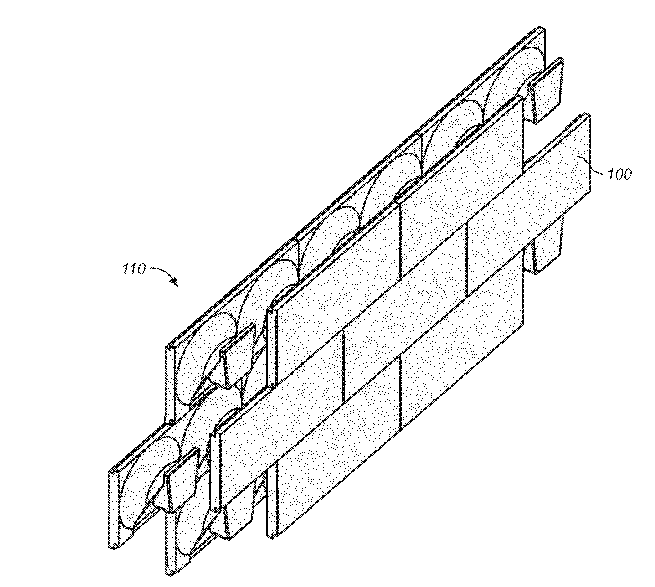
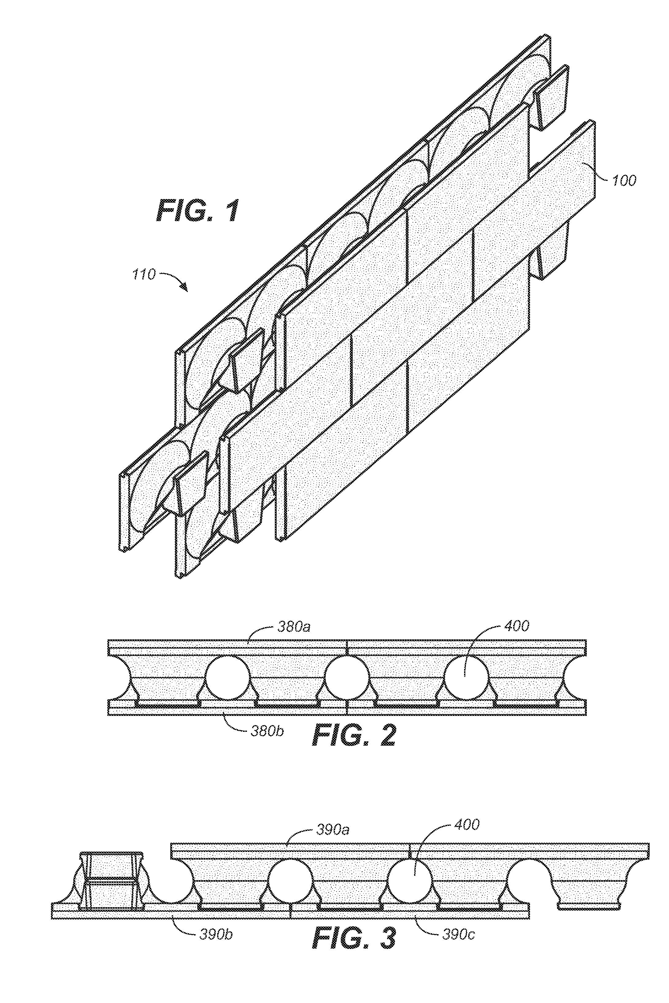
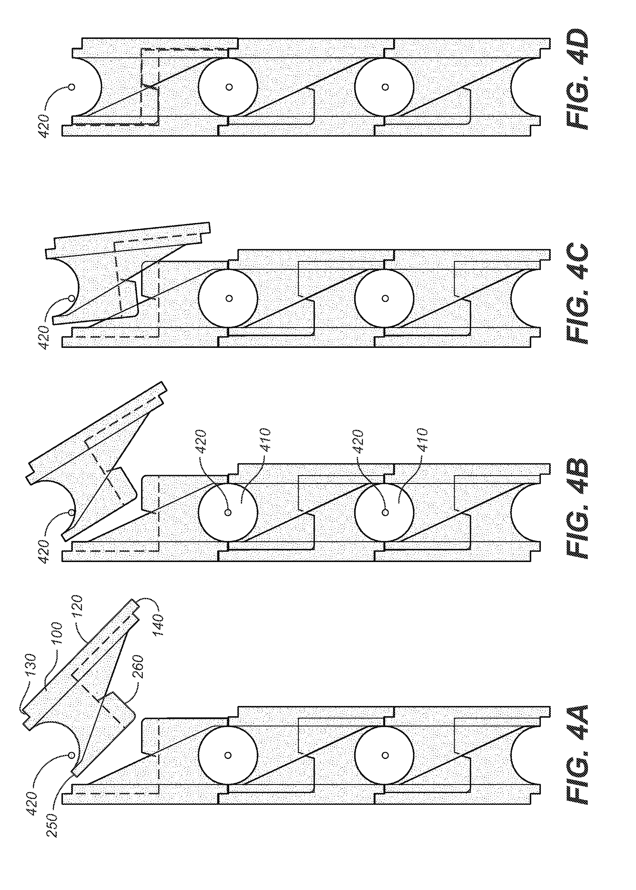
[0055]FIG. 1 shows a wall constructed with three courses using the first preferred embodiment 100 of the cementitious block of the present invention, the details of which are shown in FIGS. 5-12. FIGS. 1-4D show how the block elements of the first preferred embodiment combine to form interlocking units for such a wall construction. FIGS. 13-20 depict a second preferred embodiment of the present invention.

[0056]Referring first to FIGS. 5-12, there is shown various views of one of the preferred embodiments of the cementitious block of the present invention. These views collectively show that in its most essential form, the block includes a monolithic cementitious unit 100 having a generally planar front face 120, a first edge 130, a second edge 140, a first (right) end 150, a second (left) end 160, a back face 170, and at least one male interlocking element 180. Preferably each block includes two male interlocking elements 180a, 180b. Each male interlocking element comprises a taperin...

embodiment 500

[0061]Referring now to FIGS. 13-20, there is shown a second preferred embodiment 500 of the cementitious block of the present invention. This block includes all the structural features of the above-described (alternative) embodiment, including a monolithic cementitious block 510 having a generally planar front face 520, a first edge 530, a second edge 540, a first end 550, a second end 560, a back face 570, and at least one male interlocking element 580. Again, preferably each block includes two male interlocking elements 580a, 580b.

[0062]Male interlocking elements include elements identical to those of the first preferred embodiment, including a tapering conical leg which projects and extends outwardly into an integral ankle portion, which, in turn, expands into a shoe portion, which has a flat sole, a lateral upper portion, a medial upper portion, a flat toe, a heel, a vamp, and a topline. The edge of the adjoining upper and sole portions define a beveled feather, and the edges o...


PUM


Abstract

A stackable masonry unit having male and female elements that cooperate with complementary female and male elements on identical, opposing, adjoining units to create an interlocking two- or three-unit module from single design element. Each interlocking module comprises a portion of a course in a block wall made of cementitious material, e.g., a concrete masonry unit or insulating concrete foam.

Description

CROSS REFERENCES TO RELATED APPLICATIONS[0001]The present application claims the benefit of the filing date of U.S. Provisional Patent Application Ser. No. 61 / 090,113, filed Aug. 19, 2008 (Aug. 19, 2008).STATEMENT REGARDING FEDERALLY SPONSORED RESEARCH OR DEVELOPMENT[0002]Not applicable.THE NAMES OR PARTIES TO A JOINT RESEARCH AGREEMENT[0003]Not applicable.INCORPORATION-BY-REFERENCE OF MATERIAL SUBMITTED ON A COMPACT DISC[0004]Not applicable.BACKGROUND OF THE INVENTION[0005]1. Field of the Invention[0006]The present invention relates to unit-shaped masonry blocks and / or EPS foam blocks, and more particularly to stackable block unit configurations, and still more particularly to a stackable block units having male and female elements that cooperate with complementary female and male elements on identical, opposing, adjoining and / or interlocking blocks (i.e., units) to create an interlocking two- or three-unit module from a single design element. Each interlocking module comprises a p...

Claims


Application Information

Patent Timeline
Patent Type & Authority Applications(United States)
IPC IPC(8): E04C1/41
CPCE04B2/54E04B2/44
Inventor JENSEN, DAVID
Owner ROSENBLATT INNOVATIONS LLC
Why Eureka
Try Eureka