
Movable gas introduction structure and substrate processing apparatus having same

Active Publication Date: 2010-02-25
TOKYO ELECTRON LTD
View PDF21 Cites 12 Cited by
  • Summary
  • Abstract
  • Description
  • Claims
  • Application Information

AI Technical Summary

Benefits of technology

[0015]In view of the above, the present invention provides a movable gas introduction structure and a substrate processing apparatus having same that can substantially reduce the particle generation probability and also acquire a high freedom of arrangement.

Problems solved by technology

As a result, it is difficult to apply the flexible tube 108 to the shower head 103 that is frequently vertically movable by a large displacement of 70 mm.
However, even nano-sized particles cannot be allowed to be present in the chamber 101 of the substrate processing apparatus 100.

Method used


Image

  • Movable gas introduction structure and substrate processing apparatus having same
  • Movable gas introduction structure and substrate processing apparatus having same
  • Movable gas introduction structure and substrate processing apparatus having same

Examples


Embodiment Construction

[0025]An embodiment of the present invention will now be described with reference to the accompanying drawings which form a part hereof.

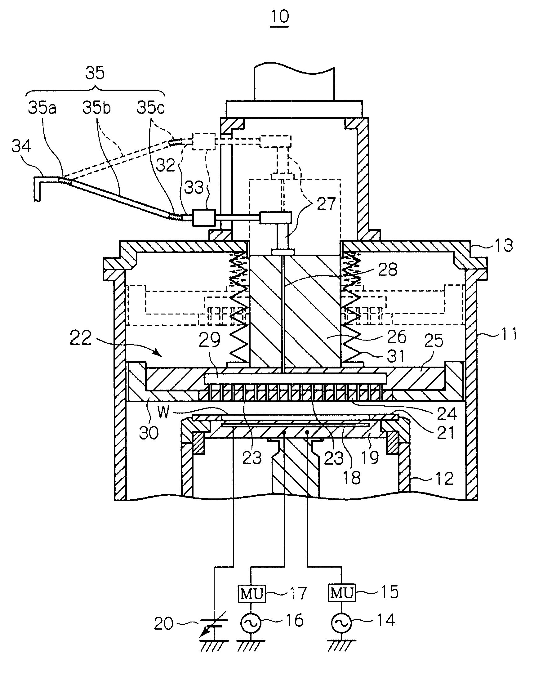
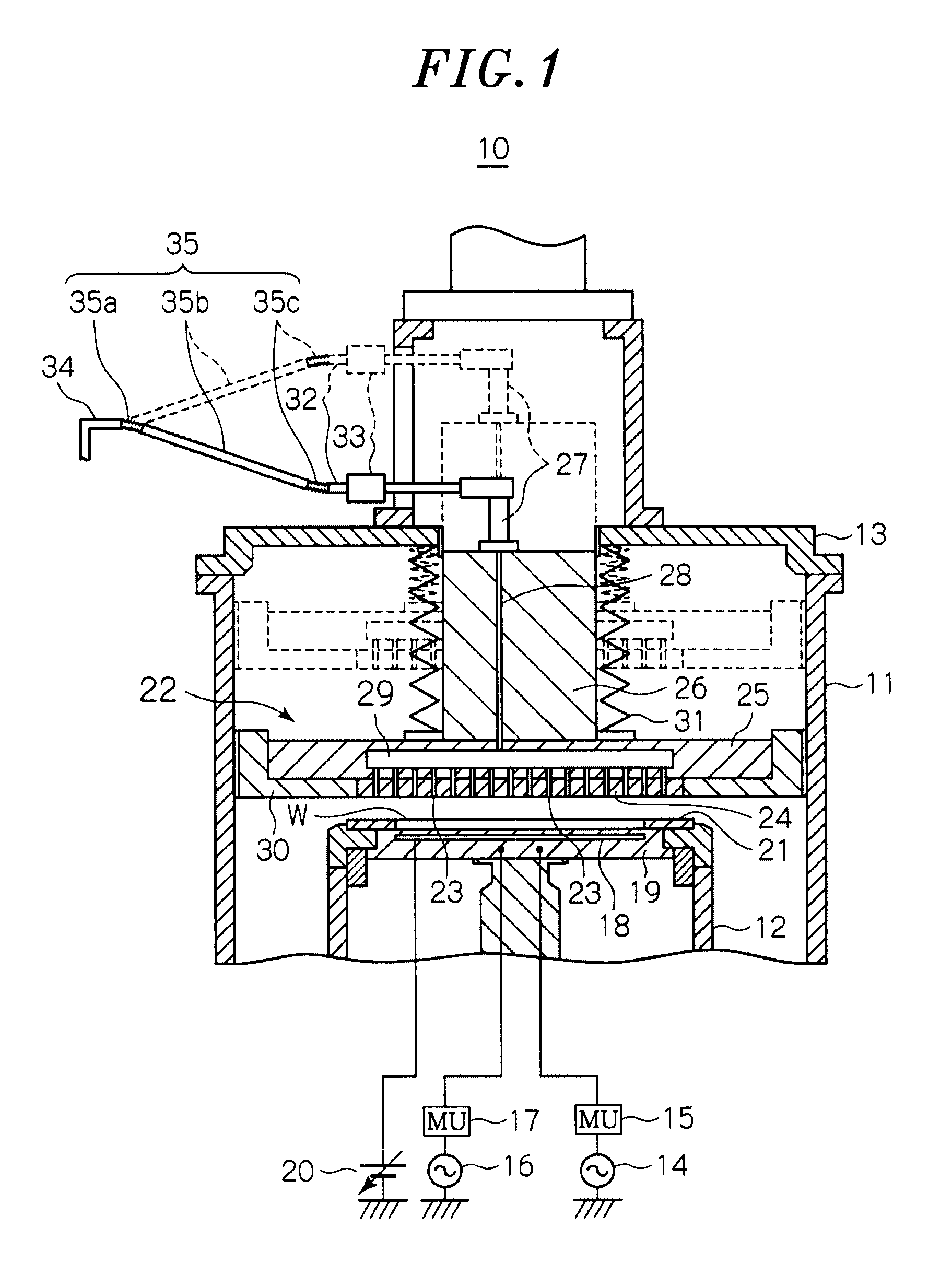
[0026]FIG. 1 is a schematic cross sectional view showing a structure of a substrate processing apparatus 10 including a movable gas introduction structure in accordance with an embodiment of the present invention. The substrate processing apparatus 10 is configured to subject a wafer to an etching processing.

[0027]In FIG. 1, the substrate processing apparatus 10 includes: a cylindrical chamber (processing chamber) 11 configured to accommodate a wafer W having a diameter of, e.g., 300 mm therein; a cylindrical susceptor (mounting table) 12 arranged at a lower portion of the chamber 11 and mounting the wafer W for semiconductor devices; and an openable cylindrical cover unit 13 configured to cover an upper portion of the chamber 11.

[0028]The pressure inside the chamber 11 is lowered by a turbo molecular pump (TMP) (not shown), a dry pump (DP) (not sho...


PUM

PropertyMeasurementUnit
Lengthaaaaaaaaaa
Structureaaaaaaaaaa
Frequencyaaaaaaaaaa

Abstract

In a gas introduction structure that is reciprocatingly movable in a predetermined direction, a processing gas introduction system is configured to introduce a processing gas into a processing chamber in which a substrate is subjected to a predetermined processing under a clean atmosphere; and a processing gas supply line is configured to be connected to the processing gas introduction system and an external processing gas supply source to supply the processing gas from the processing gas supply source to the processing gas introduction system, mutual relative positions of the processing gas supply source and the processing gas introduction system being changed. The processing gas supply line includes: a first bendable portion connected to the processing gas supply source; a second bendable portion connected to the processing gas introduction system; and a non-bendable pipe interposed between the first bendable portion and the second bendable portion.

Description

CROSS-REFERENCE TO RELATED APPLICATIONS[0001]This application claims priority to Japanese Patent Application No. 2008-285792 filed on Nov. 6, 2008, the entire contents of which are incorporated herein by reference.FIELD OF THE INVENTION[0002]The present invention relates to a movable gas introduction structure and a substrate processing apparatus having same; and, more particularly, to a movable gas introduction structure including a processing gas supply line that is connected to a fixed gas supply source and a substrate processing apparatus having same.BACKGROUND OF THE INVENTION[0003]A substrate processing apparatus, in which a substrate, i.e., a semiconductor wafer, is subjected to a plasma processing, includes: a chamber for accommodating the wafer therein and being capable of lowering the pressure inside the chamber; a susceptor (mounting table) arranged at a lower portion of the chamber; and a shower head arranged to face the mounting table in the chamber. The wafer is mounte...

Claims


Application Information

Patent Timeline
IPC IPC(8): H01L21/465C23C16/00
CPCH01J37/3244
Inventor HAYASHI, DAISUKE
Owner TOKYO ELECTRON LTD
Learn More